
Deepwater suction-type gravity foundation and deepwater mounting device and deepwater mounting method thereof

A technology of installation device and installation method, which is applied in infrastructure engineering, construction and other directions, can solve the problem of lack of installation of suction-type gravity foundation, etc., and achieve the effects of simple and easy transportation, installation and construction, cost saving and simple structure.

Active Publication Date: 2014-02-26
LICE SCI & TECH SHANGHAI
View PDF6 Cites 8 Cited by
  • Summary
  • Abstract
  • Description
  • Claims
  • Application Information

AI Technical Summary

Problems solved by technology

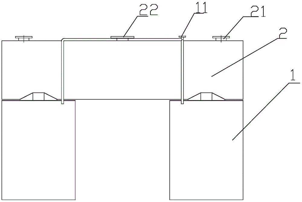
[0007] In view of the above-mentioned shortcomings of the prior art, the purpose of the present invention is to provide a deep water suction gravity foundation and its deep water installation device and deep water installation method, which are used to solve the lack of installation of suction gravity foundations in deep water areas in the prior art. The problem

Method used


Image

  • Deepwater suction-type gravity foundation and deepwater mounting device and deepwater mounting method thereof
  • Deepwater suction-type gravity foundation and deepwater mounting device and deepwater mounting method thereof
  • Deepwater suction-type gravity foundation and deepwater mounting device and deepwater mounting method thereof

Examples


Embodiment Construction

[0056] The implementation of the present invention will be illustrated by specific specific examples below, and those skilled in the art can easily understand other advantages and effects of the present invention from the contents disclosed in this specification.

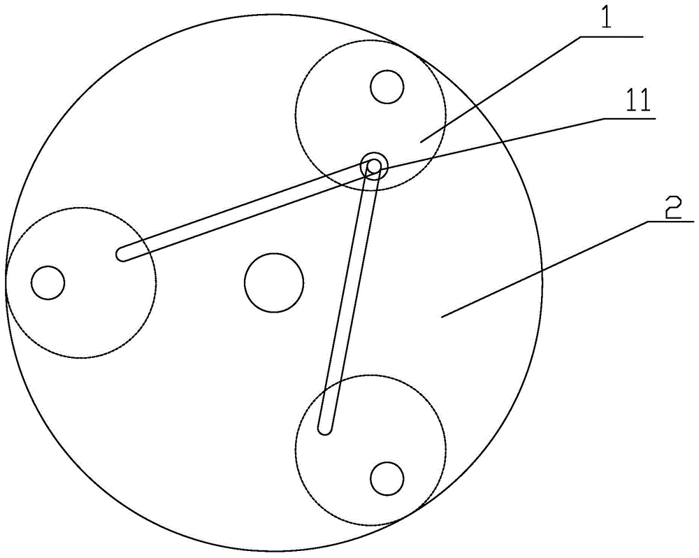
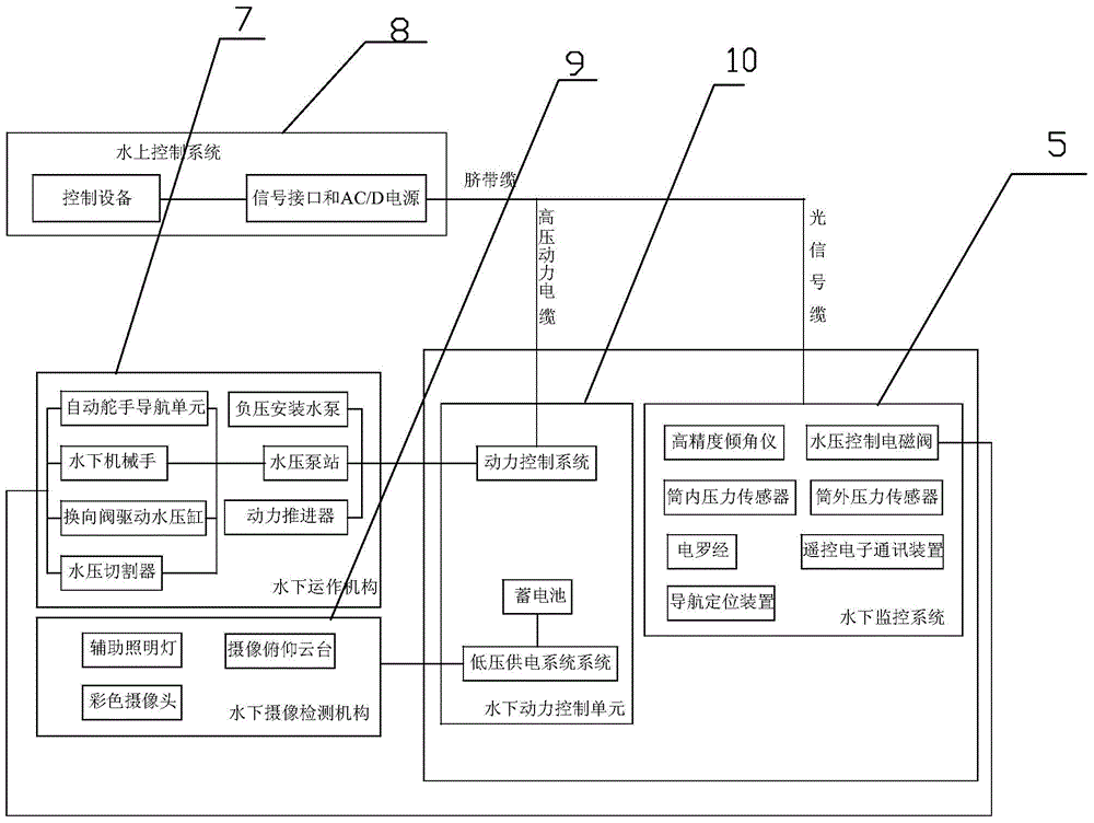
[0057] see Figure 1 to Figure 9 . It should be noted that the structures, proportions, sizes, etc. shown in the drawings attached to this specification are only used to match the content disclosed in the specification, for those who are familiar with this technology to understand and read, and are not used to limit the implementation of the present invention. Limiting conditions, so there is no technical substantive meaning, any modification of structure, change of proportional relationship or adjustment of size, without affecting the effect and purpose of the present invention, should still fall within the scope of the present invention. The disclosed technical content must be within the scope covered. At the sa...


PUM


Abstract

The invention provides a deepwater suction-type gravity foundation and a deepwater mounting device and a deepwater mounting method thereof. The deepwater suction-type gravity foundation comprises suction piles and a weight box arranged on the suction piles, a drainage outlet, a sand filling inlet and a pump connector are arranged at the top of the weight box, the drainage outlet and the sand filling inlet are communicated with the weight box, and the pump connector is communicated with the suction piles. Therefore, field operation is enabled to be simple and convenient, and cost is saved.

Description

technical field [0001] The invention relates to the field of underwater foundation construction, in particular to a suction gravity foundation for deep water, a deep water installation device and a deep water installation method thereof. Background technique [0002] The suction pile technology was proposed in the 1960s, and it was only applied in the engineering century in the early 1980s. Because the suction pile technology is simple in construction and can be recycled and reused, it is favored by people. Therefore, various domestic research And the construction unit pays more attention to the suction pile technology. Suction piles are rigid short piles that are pressed into the soil by water pressure. Its basic structure is a cylinder with a closed upper end and an open lower end. Therefore, suction piles are also called suction anchors, barrel foundations or barrel foundations. , and has a water hole connected to the pump system on the top. [0003] The piling principl...

Claims


Application Information

Patent Timeline
IPC IPC(8): E02D27/12E02D27/52
Inventor 刘爱永范会渠缪清明
Owner LICE SCI & TECH SHANGHAI
Learn More