Pipe-in-pipe structure and machining method and installing method thereof

An installation method and pipe-in-pipe technology, which is applied in building construction, roof drainage, construction, etc., can solve problems such as precision deviation, inability to use, and narrow operating space, and achieve improved processing accuracy, improved adjustability, and convenient docking Effect

Active Publication Date: 2014-02-26
CHINA CONSTR STEEL STRUCTURE ENG CO LTD
View PDF5 Cites 9 Cited by
  • Summary
  • Abstract
  • Description
  • Claims
  • Application Information

AI Technical Summary

Problems solved by technology

[0005] (1) During construction, operators need to enter inside the outer pipe (steel pipe column). However, the layout of pipes and stiffeners inside the outer pipe is complicated, and the operating space is narrow. The safety of operators and the connection quality of the inner pipe (rainwater pipe) cannot be effectively guaranteed
[0006] (2) After the outer tube is installed and fixed, it needs to be connected to the inner tube, which requires very high precision. Once the accuracy deviation of the outer tube or inn

Method used


Image

  • Pipe-in-pipe structure and machining method and installing method thereof
  • Pipe-in-pipe structure and machining method and installing method thereof
  • Pipe-in-pipe structure and machining method and installing method thereof

Examples


Embodiment Construction

[0037] In order to make the technical problems, technical solutions and beneficial effects to be solved by the present invention clearer, the present invention will be further described in detail below in conjunction with the accompanying drawings and embodiments. It should be understood that the specific embodiments described here are only used to explain the present invention, not to limit the present invention.

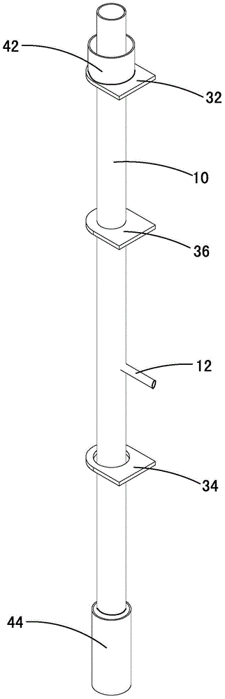
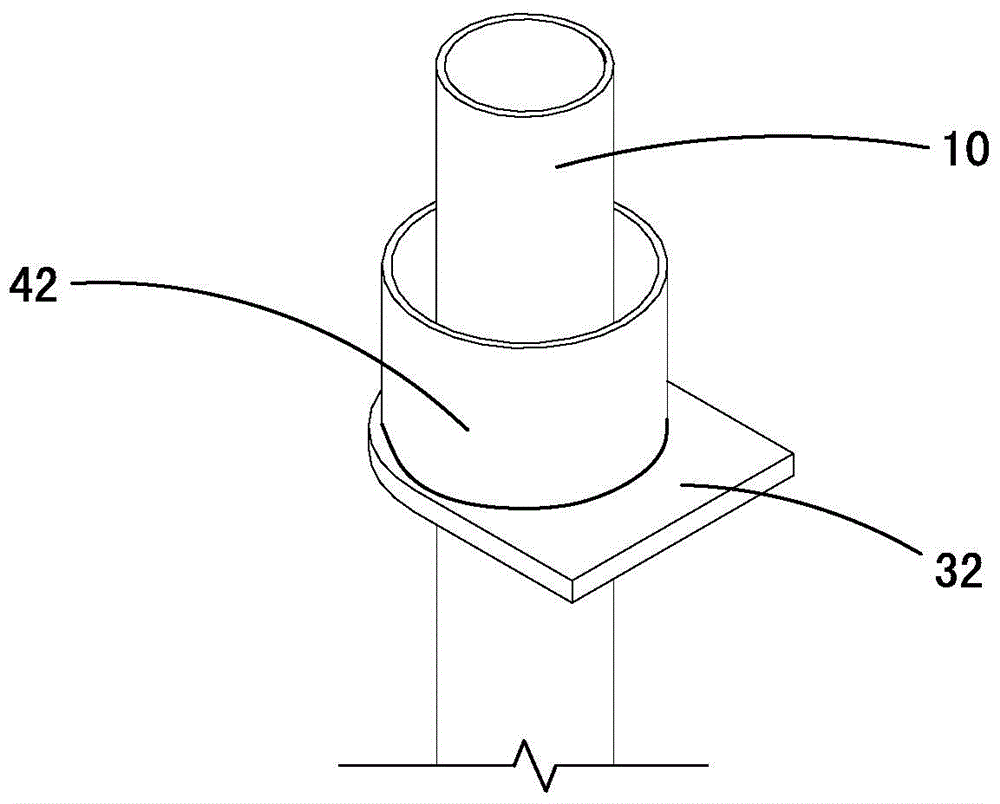
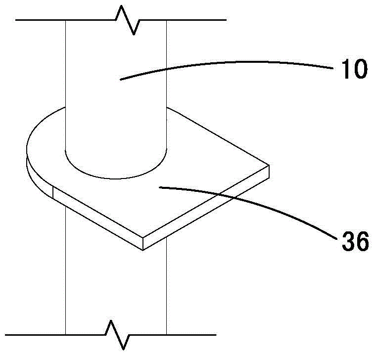
[0038] The pipe-in-pipe column provided by the embodiment of the present invention includes an outer pipe and an inner pipe, and the inner pipe is connected and fixed in the outer pipe through a plurality of connecting plates. Wherein, the outer pipe is, for example, a steel pipe column, and the inner pipe is, for example, an air conditioner condensate pipe. The butt joints of the outer tube are designed according to conventional joints, and ear plates are provided to assist in positioning during installation. A horizontal stiffener (not shown) is arranged inside ...


PUM

PropertyMeasurementUnit
Heightaaaaaaaaaa

Abstract

The invention relates to a pipe-in-pipe structure which comprises an outer pipe and an inner pipe arranged in the outer pipe, wherein a plurality of connection plates are sleeved on the inner pipe and fixed in the outer pipe, a column top sleeve and a column bottom sleeve are arranged on the inner pipe, the column top sleeve is sleeved at the top end of the inner pipe, the inner diameter of the column top sleeve is larger than the outer diameter of the column bottom sleeve, the column bottom sleeve is sleeved at the bottom end of the inner pipe, and the inner diameter of the column bottom sleeve is larger than the outer diameter of the inner pipe; the top end of the inner pipe protrudes out of the column top sleeve, and the column bottom sleeve protrudes out of the bottom end of the inner pipe. The pipe-in-pipe structure has the advantages of being high in machining precision and convenient in butt joint. The invention further provides a machining method and an installing method of the pipe-in-pipe structure.

Description

technical field [0001] The invention belongs to the field of building construction, and in particular relates to a pipe-in-pipe structure, a manufacturing method and an installation method thereof. Background technique [0002] With the vigorous development of the domestic construction industry, domestic architects began to give some new design concepts to modern buildings. Arranging equipment pipes in structural columns not only optimizes the appearance of the building, but also reduces the chance of equipment pipes being damaged by external forces during use. At the same time, it provides a new way of thinking for the layout of construction equipment pipes. It has been widely used in reinforced concrete in recent years. in structure. [0003] Based on this idea, some designers in steel structure engineering also set equipment pipelines in steel pipe columns. Structural steel pipe columns and equipment pipes must be butted in sections during construction. During the const...

Claims


Application Information

Patent Timeline
IPC IPC(8): E04D13/08E04G21/14
Inventor 贺印王朝阳刘翠杨盛斌刘海潮吴彬夏钦章少君郑峰彭建怀黄祥林
Owner CHINA CONSTR STEEL STRUCTURE ENG CO LTD
Why Eureka
Try Eureka