
Hoisting system of drilling machine

A technology for lifting systems and drilling rigs, applied to drill pipes, drill pipes, drilling equipment, etc., to achieve the effect of convenient transportation and simple structure

Inactive Publication Date: 2014-02-26
河北华北石油荣盛机械制造有限公司
View PDF2 Cites 3 Cited by
  • Summary
  • Abstract
  • Description
  • Claims
  • Application Information

AI Technical Summary

Problems solved by technology

[0004] The purpose of the present invention is to provide a drilling rig lifting system to solve the technical problems of drilling lifting equipment, such as simple structure, easy installation and transportation, safe and reliable operation, and the ability to press down the load to meet the drilling requirements in special working conditions.

Method used


Image

  • Hoisting system of drilling machine
  • Hoisting system of drilling machine
  • Hoisting system of drilling machine

Examples


example 1

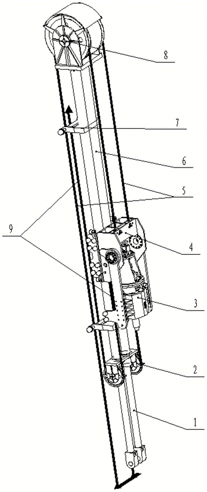
[0025] Example 1, taking a lifting system as an example, further describes the present invention in detail. see figure 1 , the main body of the lifting device of the drilling rig is an inverted hydraulic cylinder composed of a hydraulic cylinder (6) and a hydraulic cylinder rod (1), which is installed on the bottom plate of the derrick through a pin shaft. The weight generated in the derrick acts on the bottom of the derrick, with a low center of gravity and good stability.

[0026] The hydraulic cylinder in the lifting system is installed upside down inside the derrick, and the piston rod (1) is connected with the hinge seat pin on the derrick connecting plate. The force generated by the hydraulic cylinder directly acts on the connecting plate at the lower part of the derrick. The main force, the main function of the upper derrick is to provide guide rails for the movement of the power head and the lifting device and to withstand the reaction torque generated during the dril...

Embodiment 2

[0033] Embodiment 2, taking the working principle of the lifting system as an example, further introduces in detail, in order to deeply understand the lifting system of the present invention.

[0034] Lifting process:

[0035] When the hydraulic cylinder is stretched out, one end of the lifting wire rope is connected to the pulley, and the other end goes around the pulley block of the upper lifting assembly and is fixed at the lower end of the derrick. The hydraulic cylinder extends to a maximum stroke of 7 meters, and the upper lifting pulley block (moving pulley) rises 7 meters. According to the working principle of the movable pulley, the steel wire rope drives the pulley and the power head to rise up to a distance of 14 meters, thereby realizing the doubling of the stroke. The drill string is lifted by the force generated by the hydraulic pressure of the plug chamber of the hydraulic cylinder. During this process, the steel wire rope is pressed down and moves accordingly,...


PUM


Abstract

The invention discloses a hoisting system of a drilling machine. The hoisting machine is mainly composed of an upper lifting assembly, a lower lifting assembly, a hydraulic cylinder, a centering wheel assembly, an uplifting steel wire rope, a pressing-down steel wire rope, a pulley and a power head. The hydraulic cylinder is mounted on the inner side of the a derrick in an inverted manner, a piston rod (1) is connected with a hinge mount pin on a derrick connection plate, the upper lifting assembly (8), and the lower lifting assembly (2) and the centering wheel assembly (7) are respectively in bolted connection with a hydraulic cylinder barrel (6). By the hoisting system, multiplication of a stroke is realized, good stability is guaranteed, and migration length of drilling machine equipment is shortened; capability of down-pressing load is achieved, and drilling requirements under special working conditions can be met; the hoisting system is simple in structure and capable of taking the place of a conventional lifting system for winch systems, crown blocks, traveling blocks and hooks.

Description

technical field [0001] The invention relates to a drilling rig lifting system, which belongs to the field of drilling and workover equipment, and is especially suitable for inclined well drilling rigs, vertical well drilling rigs and well workover rigs. Background technique [0002] At present, the hoisting system of domestic drilling rigs is mainly wound by a winch, and the steel wire rope passes through a pulley block composed of a crown block and a traveling block to drive the hook to lift or lower the pipe string. This kind of lifting device has the disadvantages of complex structure, difficult disassembly and transportation, etc. What is more worth mentioning is that this kind of lifting system only has the function of lifting the load, and does not have the function of pressing the load down. [0003] For this reason, a drilling rig lifting system is designed, which has a compact structure and can be applied not only to vertical well drilling rigs but also to inclined ...

Claims


Application Information

Patent Timeline
IPC IPC(8): E21B19/00
Inventor 李慎奎刘士岩王建伟王坤青王薇
Owner 河北华北石油荣盛机械制造有限公司
Learn More