Actuating mechanism of hydraulic automatic clutch

An automatic clutch and actuator technology, applied in non-mechanical drive clutches, clutches, mechanical equipment, etc., can solve the problems of high vibration intensity, short life, inaccurate positioning, etc., to increase the service life of the mechanism, good mechanical rigidity, and positioning precise effect

Inactive Publication Date: 2014-02-26
南宁市西真电子科技开发有限公司
View PDF4 Cites 4 Cited by
  • Summary
  • Abstract
  • Description
  • Claims
  • Application Information

AI Technical Summary

Problems solved by technology

At present, the actuators used in clutches include hydraulic control mechanism and electromechanical control mechanism. Among them, the hydraulic control mechanism has stable transmission, soft clutch combination, and high transmission efficiency, but it has high requirements on oil quality, sealing and operating environment; The mechanica

Method used


Image

  • Actuating mechanism of hydraulic automatic clutch
  • Actuating mechanism of hydraulic automatic clutch
  • Actuating mechanism of hydraulic automatic clutch

Examples


Embodiment

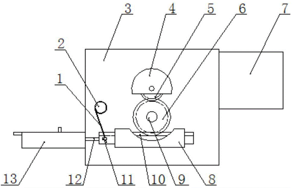
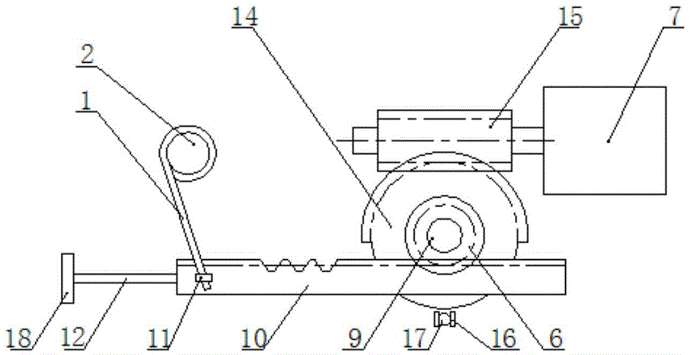
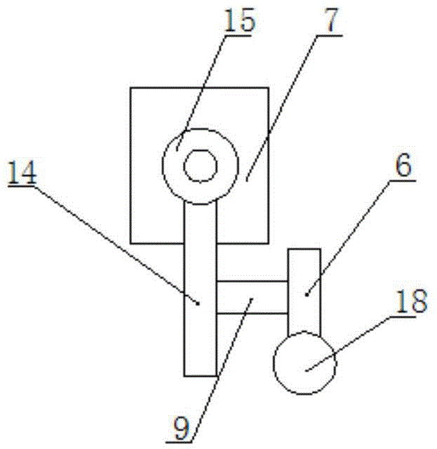
[0041] Such as Figure 1 to Figure 3 As shown, an actuator of a hydraulic automatic clutch includes: a transmission box 3, a pair of worm and gear mechanisms are arranged in the transmission box 3, and its worm 15 is driven by a motor 7, and the motor 7 is a 12V brushed DC motor, so it can Power is directly supplied by the car battery, and the motor 7 is fixedly arranged on the right side outer wall of the transmission box 3, and its output shaft extends into the transmission box 3 and is connected with the worm 15 to drive the worm 15 to rotate, and the worm gear meshed with the worm 15 for transmission 14 is an incomplete worm gear, which is fixed on the transmission shaft 9, the transmission shaft 9 is perpendicular to the worm screw 15, the transmission shaft 9 is installed in the transmission case 3 in a rotatable manner through the bearing, and one end of it stretches out from the transmission case 3 The upper wall surface, and this end is fixedly connected with the tran...


PUM


Abstract

Disclosed is an actuating mechanism of a hydraulic automatic clutch. The actuating mechanism comprises a master cylinder, a driving mechanism and a position detection device, an output end of the driving mechanism is connected with a piston of the master cylinder, the position detection device is used for detecting moving information of the driving mechanism, the driving mechanism comprises a transmission box, a driving member, a pair of worm-gear mechanism, a limiting device and a pair of gear-rack mechanism, the driving member is arranged on a first outer side face of the transmission box, the worm-gear mechanism is mounted in an inner cavity of the transmission box, a worm of the worm-gear mechanism is connected with an output shaft of the driving member, a worm gear of the worm-gear mechanism is an incomplete worm gear and is fixedly arranged on a transmission shaft, one end of the transmission shaft extends out of a second outer side face of the transmission box, the limiting device is arranged in the transmission box and corresponds to one side, without gear teeth, of the worm gear, the gear-rack mechanism is arranged on the second outer side face, a gear of the gear-rack mechanism is fixedly arranged at one end, extending out of the second outer side face, of the transmission shaft, and one end of a rack is connected with the piston through a connecting rod. The actuating mechanism is accurate in clutch positioning, resistant to vibration and good in mechanical structure rigidity.

Description

technical field [0001] The invention relates to an actuator of a hydraulic automatic clutch. Background technique [0002] The hydraulic automatic clutch is a device that realizes automatic control of the clutch through mechanical, electronic, hydraulic and other means. It can calculate the best accelerator clutch cooperation through the computer to achieve the best control stability, thereby replacing manual clutch operation. At present, the actuators used in clutches include hydraulic control mechanism and electromechanical control mechanism. Among them, the hydraulic control mechanism has stable transmission, soft clutch combination, and high transmission efficiency, but it has high requirements on oil quality, sealing and operating environment; The mechanical control mechanism has simple structure, low cost and low energy consumption, but due to the high vibration intensity and high temperature of the actuator when it is working, its life is short, and the moment of iner...

Claims


Application Information

Patent Timeline
IPC IPC(8): F16D29/00
Inventor 李廷彦
Owner 南宁市西真电子科技开发有限公司
Why Eureka
Try Eureka