System for detecting error and guiding error correction and method thereof

An error correction and error detection technology, which is applied in the field of position detection systems, can solve problems such as high installation accuracy requirements, high cost, and inability to determine errors, and achieve the effects of low installation accuracy, simple structure, and convenient installation

Active Publication Date: 2014-02-26
SHENZHEN CHINA STAR OPTOELECTRONICS TECH CO LTD
View PDF6 Cites 23 Cited by
  • Summary
  • Abstract
  • Description
  • Claims
  • Application Information

AI Technical Summary

Problems solved by technology

However, the position detection system cannot detect the left, right, up, and down position deviation of the target in front, or it cannot determine whether the error is the direction of position deviation to the left, right, upward, or downward relative to the center, nor can it guide the device to adjust the er

Method used


Image

  • System for detecting error and guiding error correction and method thereof
  • System for detecting error and guiding error correction and method thereof
  • System for detecting error and guiding error correction and method thereof

Examples


Embodiment Construction

[0022] The present invention will be further described below in conjunction with the accompanying drawings and specific embodiments.

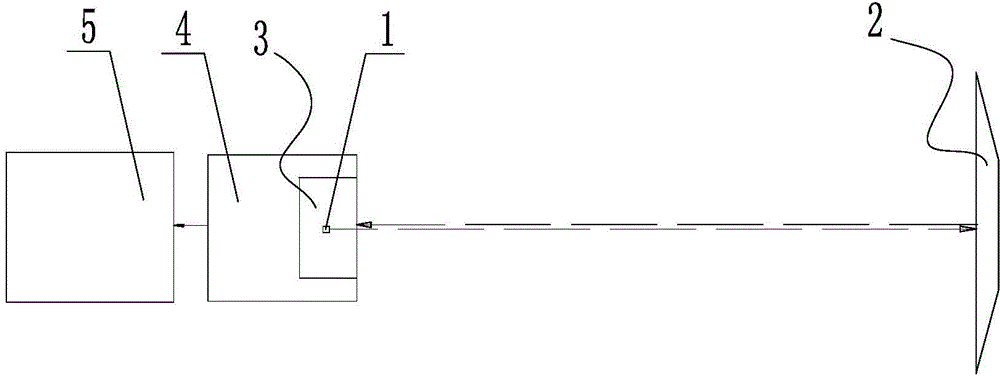
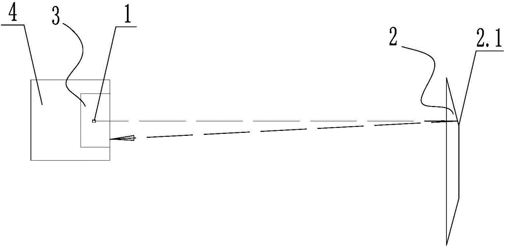
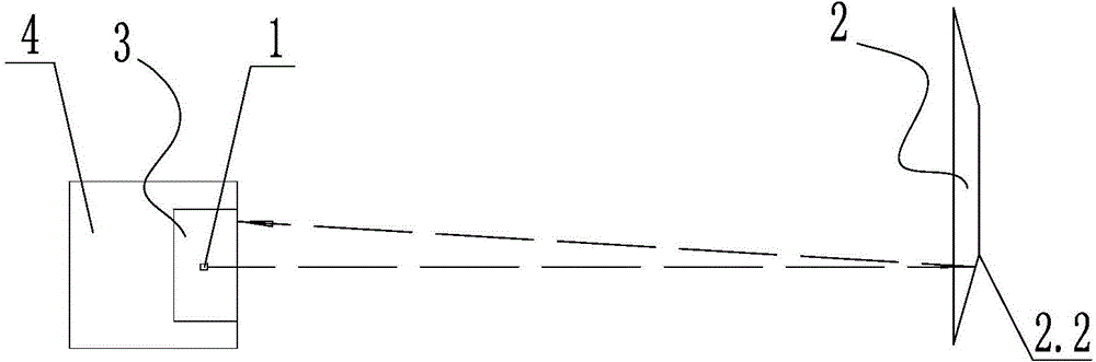
[0023] Such as figure 1 Shown is a specific embodiment of the system of the present invention for detecting errors and directing error correction. In this embodiment, the system for detecting errors and directing error correction includes:

[0024] Laser emitter 1, used to emit point laser;

[0025] The reflector 2 is used for specular reflection of the laser light emitted by the laser emitter 1 .

[0026] The photosensitive plate 3 is used to detect the laser signal reflected by the reflective plate 2 . In this embodiment, the photosensitive plate 3 is a CCD photosensitive plate.

[0027] A signal processor 4, electrically connected to the photosensitive plate 3, for processing the signal transmitted by the photosensitive plate 3;

[0028] The equipment control center 5 is electrically connected with the signal processor 4 and displays th...


PUM


Abstract

The invention discloses a system for detecting an error and guiding error correction and a method thereof. The system comprises a laser transmitter used for transmitting point laser, a reflection plate used for carrying out specular reflection on laser emitted by the laser transmitter, a photographic plate used for detecting the laser signal emitted by the reflection plate, a signal processor which is electrically connected with the photographic plate and is used for processing the signal transmitted by the photographic plate, a device control center which is electrically connected with the signal processor and displays the result of the signal processor, and a signal processor which receives a reflection laser point position signal transmitted by the photographic plate, compares the signal with a stored center point position, calculates whether a target object position has deviation and a deviation direction, and carries out real-time transmission to the device control center to carry out deviation correction. The system is used for detecting up, down, left and right errors relative to the center and guiding error correction, and the system has the advantages of simple structure, low installation accuracy requirement and low cost.

Description

technical field [0001] The invention relates to a position detection system, in particular to a system and method for detecting errors and guiding error correction. Background technique [0002] The existing position detection system generally adopts the photoelectric switch reflector type. It generally includes a mechanical mobile platform, an infrared light source and a reflector. The infrared light source and the reflector are arranged on the mechanical mobile platform. The reflector adopts an uneven reflective surface. It uses diffuse reflection to confirm whether there is an error in the detection target ahead, and is generally used to detect whether the target is in front. However, the position detection system cannot detect the left, right, up, and down position deviation of the target in front, or it cannot determine whether the error is the direction of position deviation to the left, right, upward, or downward relative to the center, nor can it guide the device to...

Claims


Application Information

Patent Timeline
IPC IPC(8): G01B11/00
CPCG01B11/26
Inventor 杨卫兵吴俊豪林昆贤汪永强舒志优齐明虎陈增宏杨国坤蒋运芍李晨阳子
Owner SHENZHEN CHINA STAR OPTOELECTRONICS TECH CO LTD
Why Eureka
Try Eureka