Supersonic wave wind measurement sensor pillar structure

A wind sensor, ultrasonic technology, applied in the direction of instruments, measuring devices, fluid velocity measurement, etc., can solve the problems of unfavorable sensor measurement, easy to be affected by leaves, paper, precipitation, etc., to reduce stray signals, overcome The effect of the influence of the signal received by the transducer

Inactive Publication Date: 2014-02-26
PLA UNIV OF SCI & TECH +1
View PDF4 Cites 0 Cited by
  • Summary
  • Abstract
  • Description
  • Claims
  • Application Information

AI Technical Summary

Problems solved by technology

[0004] There are two main ways to install the transducers of the existing ultrasonic wind sensors: one is to support the probes through four poles, and the four probes are completely exposed to the air. This structure makes the work in the middle of the four transducers The area is easily affected by leaves, paper, precipitation, etc.; the other installation method is that the transducer is fixed on the top of a column, and the top cover is installed on the top through a pole. , snow, etc. are easy to accumulate on it and affect the normal operation of the transducer
Both methods have disadvantages to the measurement of the sensor

Method used


Image

  • Supersonic wave wind measurement sensor pillar structure

Examples


Embodiment Construction

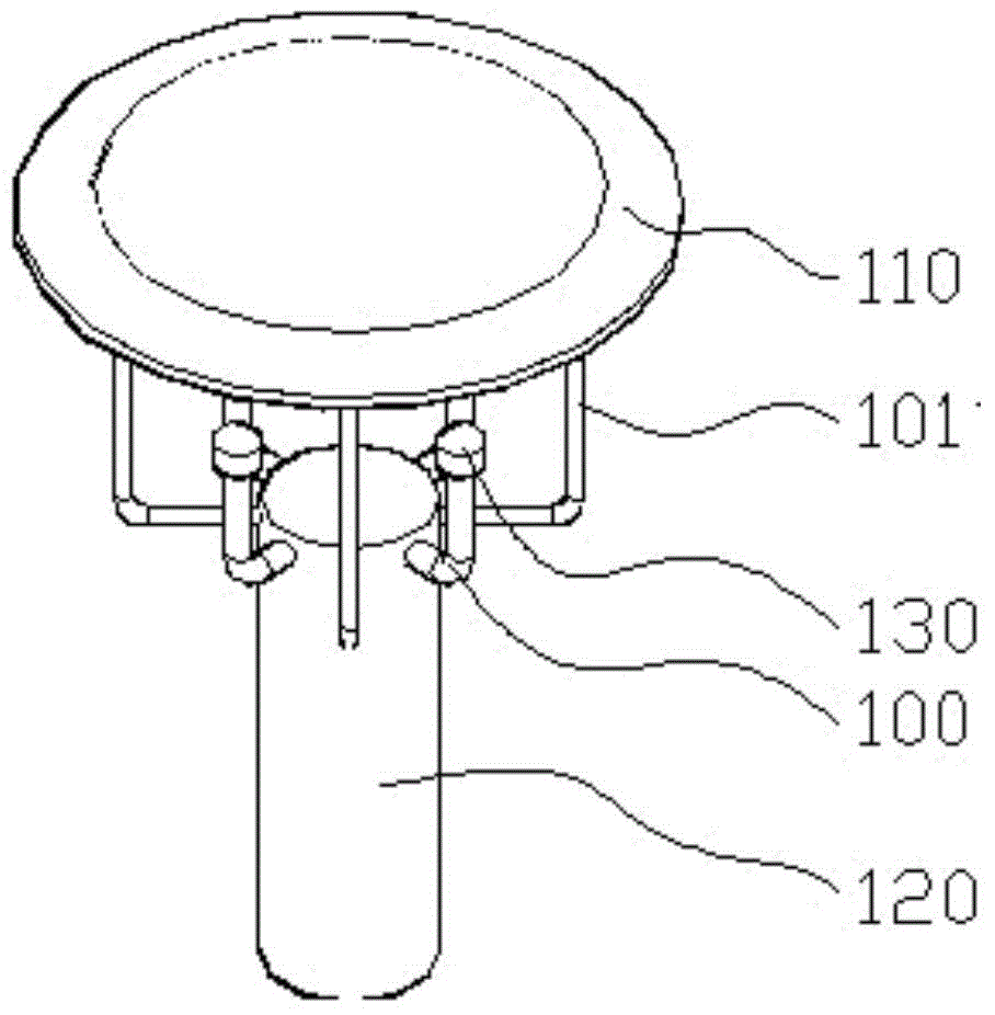
[0011] Depend on figure 1 It can be seen that the present invention is composed of a transducer pole 100, a roof pole 101, a roof 110, a cylinder 120, a transducer 130 and the like.

[0012] In the present invention, the outer side of the upper part of the cylinder 120 is connected to the transducer struts 100, and the (four) transducer struts form an orthogonal angle of 90 degrees (or struts protruding obliquely upward) from the cylinder 120 Taken out, the transducer 130 used for measurement is installed on the top of the transducer strut, which is higher than the top of the column 120 by more than 15cm or more than 20cm from the top of the column; the diameter of the transducer strut is 1 / 2 of the diameter of the column 120 Within a certain distance, the transducer 130 is separated from the cylinder 120 to ensure that the cylinder interferes less with the transducer. The outer side of the upper part of the cylinder 120 is connected to the top cover strut 110, and the four t...


PUM


Abstract

Provided is a supersonic wave wind measurement sensor pillar structure. The supersonic wave wind measurement sensor pillar structure comprises a cylinder, energy transducer poles, supersonic wave wind measurement energy transducers, top cover poles and a top cover. The outer side of the upper portion of the cylinder is connected with the energy transducer poles; the top portions of the energy transducer poles are provided with the measurement energy transducers; the energy transducers are each spaced at a certain distance from the cylinder; the outer side of the upper portion of the cylinder is connected with the top cover poles; the top portions of the top cover poles are connected with the top cover; the top cover is spaced at a certain distance from above the energy transducers; and the energy transducers are disposed within the covering scope of the top cover. According to the invention, the heights of the energy transducers are lifted by the energy transducer poles so that the working of the energy transducers is prevented from being affected due to sand and dust and snow accumulation around the energy transducers; and at the same time, due to the effects of the top cover, the working area of the four energy transducers are not interfered by foreign materials including leaves, paper slices and the like, and rainfall.

Description

technical field [0001] The invention belongs to the field of meteorological measuring instruments, in particular to a pillar structure of an ultrasonic wind measuring sensor. Background technique [0002] Ultrasonic wind sensors are used in the measurement of wind direction and speed, especially in meteorology, energy, environmental protection, agriculture and forestry and other places. [0003] The working principle of the ultrasonic wind sensor is: use the time difference of ultrasonic wave propagation in the downwind and headwind to calculate the wind speed component along the ultrasonic propagation direction, and measure the wind speed and direction simultaneously through the combination of ultrasonic transducers in pairs. Generally, two pairs of four ultrasonic transducers are used to form an orthogonal mode. In a pair of ultrasonic transducers, when one transmits ultrasonic waves, the other receives ultrasonic waves. [0004] There are two main ways to install the tra...

Claims


Application Information

Patent Timeline
Patent Type & Authority Applications(China)
IPC IPC(8): G01P5/24G01P1/00
Inventor 孙学金卫克晶杨启东成哲生邹中凯王晓蕾赵世军刘磊
Owner PLA UNIV OF SCI & TECH
Why Eureka
Try Eureka