Field calibration method for radiated emission measurement antenna of electromagnetic compatibility experiment

An electromagnetic compatibility and field calibration technology, applied in measuring devices, measuring electrical variables, instruments, etc., can solve the problems of reduced accuracy, long time required for calibration, affecting calibration accuracy, etc., to improve accuracy and ensure accuracy. Effect

Active Publication Date: 2014-02-26
BEIJING INST OF RADIO METROLOGY & MEASUREMENT
View PDF2 Cites 10 Cited by
  • Summary
  • Abstract
  • Description
  • Claims
  • Application Information

AI Technical Summary

Problems solved by technology

[0007] (1) The radiation emission measurement antenna (i.e. biconical antenna and double ridge horn antenna) is large in size, and its maximum size is greater than 1m, which is inconvenient for packaging and transportation, and the vibration during transportation may also cause the structure of the radiation emission measurement antenna change, thereby affecting the accuracy of the calibration;
[0008] (2) Calibration takes a long time, usually two weeks or even longer, and during the calibration period, the electromagnetic compatibility test cannot be carried out normally;
[0009] (3) There are often differences in the electromagnetic environment between the electromagnetic compatibility laboratory and the calibration laboratory, which may lead to a deviation between the antenna coefficient calibrated in the calibration laboratory and the actual antenna coefficient of the antenna to be tested in the electromagnetic compatibility laboratory. resulting in less accurate calibration

Method used


Image

  • Field calibration method for radiated emission measurement antenna of electromagnetic compatibility experiment
  • Field calibration method for radiated emission measurement antenna of electromagnetic compatibility experiment
  • Field calibration method for radiated emission measurement antenna of electromagnetic compatibility experiment

Examples


Embodiment Construction

[0042] The content of the invention of the present invention will be further described below in conjunction with the accompanying drawings and embodiments.

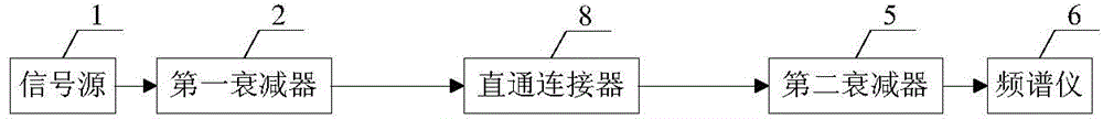
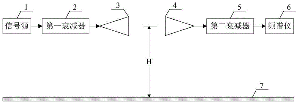
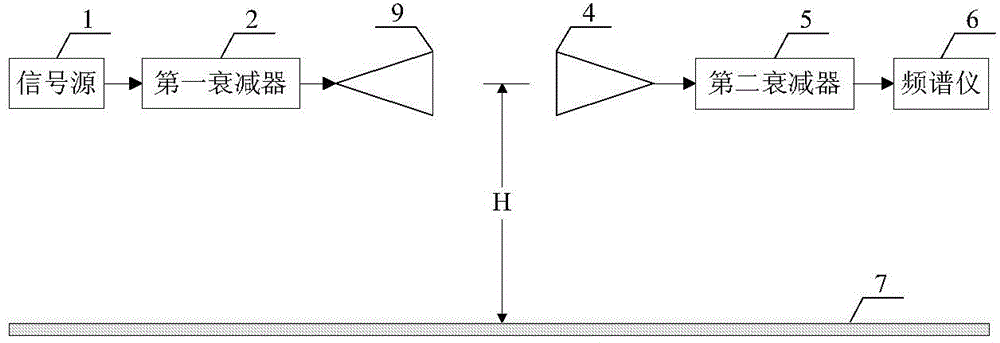
[0043] like figure 1 , figure 2 and image 3 As shown, the calibration device used in the on-site calibration method of the radiated emission measurement antenna used in the electromagnetic compatibility test provided by this embodiment includes a signal source 1, a first attenuator 2, a reference antenna 3, a transfer antenna 4, and a second attenuator 5 , a spectrum analyzer 6 , a metal floor 7 and a straight-through connector 8 .

[0044] The signal source 1 is electrically connected to the first attenuator 2 through a coaxial cable. The second attenuator 5 is electrically connected to the spectrum analyzer 6 through a coaxial cable. The signal source 1 is used to generate electromagnetic wave signals. The first attenuator 2 and the second attenuator 5 are used to eliminate the influence of the standing wave sign...


PUM


Abstract

The invention discloses a field calibration method for a radiated emission measurement antenna of an electromagnetic compatibility experiment. The field calibration method comprises the following steps that an antenna factor of a reference antenna is obtained through measurement; a first standard value of power of an electromagnetic wave signal is obtained through measurement; a first measurement value of the power of the electromagnetic wave signal is obtained through measurement; the difference value between the first standard value and the first measurement value is calculated to obtain insertion loss between the reference antenna and a transmission antenna; a second standard value of the power of the electromagnetic wave signal is obtained through measurement; a second measurement value of the power of the electromagnetic wave signal is obtained through measurement; the difference value between the second standard value and the second measurement value is calculated to obtain insertion loss between an antenna to be calibrated and the transmission antenna; the antenna factor of the antenna to be calibrated is obtained through calculation of the antenna factor of the reference antenna, the insertion loss between the reference antenna and the transmission antenna and the insertion loss between the antenna to be calibrated and the transmission antenna. The field calibration method is applied to calibration of the radiated emission measurement antenna in a 30MHz-1GHz frequency band.

Description

technical field [0001] The invention relates to the technical field of antenna calibration, in particular to an on-site calibration method for a radiation emission measurement antenna used in an electromagnetic compatibility test. Background technique [0002] In the electromagnetic compatibility test, the antenna used to measure the radiation emission of electromagnetic waves is called the radiation emission measurement antenna. In the application, the radiated emission measurement antenna is usually used to measure the field strength value of the electromagnetic field generated by the electromagnetic wave to be measured (that is, the electromagnetic field to be measured). The measurement principle is: in the electromagnetic compatibility test, the radiation emission measurement antenna will generate an induced current after sensing the electromagnetic field to be measured, and the induction current will be converted into an induced voltage at the antenna port, that is, the...

Claims


Application Information

Patent Timeline
Patent Type & Authority Applications(China)
IPC IPC(8): G01R35/00
Inventor 吴红森袁岩兴刘星汛冯英强黄建领
Owner BEIJING INST OF RADIO METROLOGY & MEASUREMENT
Why Eureka
Try Eureka