
Design method of fuel injection system for scramjet engine

A fuel injection system, scramjet technology, applied in computing, special data processing applications, instruments, etc., can solve the lack of understanding of the internal flow field of the combustion chamber, the lack of information transmission and feedback mechanisms, and the difficulty of flow at the outlet of the hypersonic intake port. and other problems, to achieve the effect of strengthening the degree of integrated design, enhancing the fuel injection and blending ability, and improving the overall performance

Active Publication Date: 2014-02-26
XIAMEN UNIV
View PDF2 Cites 20 Cited by
  • Summary
  • Abstract
  • Description
  • Claims
  • Application Information

AI Technical Summary

Problems solved by technology

There are three reasons for this: (1) In order to effectively simplify the design objectives and flow conditions; (2) There is no effective information transmission and feedback mechanism between the two independently designed sub-components; (3) The flow field at the outlet of the inlet And lack of sufficient understanding of the flow field inside the combustion chamber, for example: How to understand the influence of complex flow phenomena such as turbulent vortex characteristics on unsteady characteristics such as fuel injection and mixing in the combustion chamber?
[0006] At the same time, an obvious problem is that it is very difficult to obtain a completely uniform outlet flow for a hypersonic inlet
If only considering the uniformity of the inlet outlet, the inlet designer can only take additional measures (such as active control of the flow field) to suppress this outlet non-uniformity, which will undoubtedly bring additional flow loss

Method used


Image

  • Design method of fuel injection system for scramjet engine
  • Design method of fuel injection system for scramjet engine
  • Design method of fuel injection system for scramjet engine

Examples


Embodiment 1

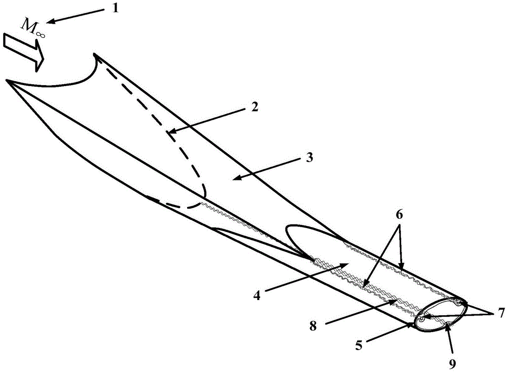
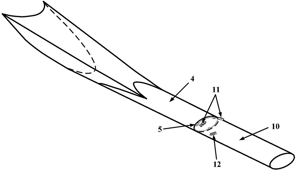
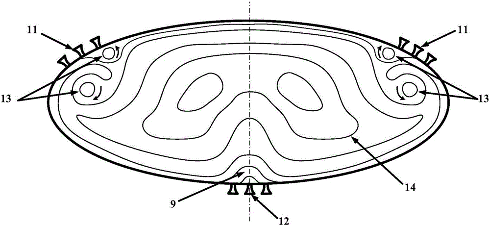
[0041] The outlet of the three-dimensional internal waverider hypersonic inlet is an ellipse with a long-to-short axis ratio of 2.5, and the inlet is similar to a V shape. There is an equal-area connection between the upstream intake port and the downstream combustion chamber, and there is no gradual or sudden transition of the geometric area. There are obvious corner vortex characteristics and low-energy / low-speed areas in the upper left corner and bottom of the intake port, respectively, and propagate to the downstream combustion chamber (such as figure 1 ). There are 3 nozzles evenly distributed in the circumferential direction in the upper left corner and the bottom of the combustion chamber (such as figure 2 and 4 ). The cross-sectional flow field at the outlet of its intake port is as follows: image 3 As shown, the fuel blending effect is obvious.

Embodiment 2

[0043] The outlet of the hypersonic three-dimensional internal waverider inlet is an ellipse with a major and minor axis ratio of 2.5, and the inlet shape is similar to a V shape. There is an equal-area connection between the upstream intake port and the downstream combustion chamber, and there is no gradual or sudden transition of the geometric area. There are obvious corner vortex characteristics and low-energy / low-speed areas in the upper left corner and bottom of the intake port, respectively, and propagate to the downstream combustion chamber (such as figure 1 ). 5 nozzles (eg Figure 5 and 7 ). The cross-sectional flow field at the outlet of its intake port is as follows: Image 6 As shown, the fuel blending effect is obvious.

Embodiment 3

[0045] The outlet of the hypersonic three-dimensional internal waverider inlet is an ellipse with a major and minor axis ratio of 2.5, and the inlet shape is similar to a V shape. There is an equal-area connection between the upstream intake port and the downstream combustion chamber, and there is no gradual or sudden transition of the geometric area. There are obvious corner vortex characteristics and low-energy / low-speed areas in the upper left corner and bottom of the intake port, respectively, and propagate to the downstream combustion chamber (such as figure 1 ). At the upper left corner and the bottom of the combustion chamber, three nozzles are distributed in the shape of a "pin" along the flow path of the corner vortex and the low energy / low velocity region respectively (such as Figure 8 and 10 ). The cross-sectional flow field at the outlet of its intake port is as follows: Figure 9 As shown, the fuel blending effect is obvious.


PUM


Abstract

The invention discloses a design method of a fuel injection system for a scramjet engine and relates to a near space vehicle. Nozzles can be distributed in the following three ways: according to flowing characteristics, the nozzles are distributed on a near vortex wall surface circumferentially, or distributed along the flowing direction, or distributed in a 'triangle' shape on the near vortex wall surface. In the component design of the existing scramjet engine, the defect that the outlet uniformity needs to be controlled as much as possible in the design of a gas inlet channel, while a non-uniform vortex structure needs to be artificially introduced in the design of a combustion chamber, is solved. By virtue of a low-energy / low-velocity zone and a corner vortex structure of the outlet of a three-dimensional internal-retraction gas inlet channel, the nozzles of a combustion chamber are reasonably arranged, the relation of flowing characteristics between the gas inlet channel and a supersonic combustion chamber is strengthened, and the fuel injection and mixing effects can be enhanced, so that the combustion efficiency is raised indirectly, and the overall performance of the scramjet engine is improved.

Description

technical field [0001] The invention relates to a near-space vehicle, in particular to a design method of a scramjet fuel injection system considering the flow characteristics of an intake port. Background technique [0002] The research on near-space vehicles is one of the focuses of the international competition for space technology, and the research on scramjets has become the top priority of the development of near-space vehicles because of its important strategic significance. The world powers represented by the United States, Russia, Germany, France and Australia are vigorously promoting their respective scramjet engine development plans. Among them, fuel injection, blending and ignition are one of the key difficulties in realizing supersonic combustion and even hypersonic flight. Since the main flow velocity in the scramjet is mostly supersonic, the incoming flow captured by the intake port usually has only a millisecond residence time in the engine flow path. It is...

Claims


Application Information

Patent Timeline
Patent Type & Authority Applications(China)
IPC IPC(8): G06F17/50
CPCY02T90/00
Inventor 尤延铖潘成剑李怡庆安平陈荣钱
Owner XIAMEN UNIV
Learn More