Metal closed solid insulation pole-mounted vacuum switch

A solid insulation and metal-enclosed technology, applied in electric switches, high-voltage/high-current switches, high-voltage air circuit breakers, etc., can solve the problems of limited use of insulating vacuum switchgear, small internal space, leakage environment, etc., to avoid water vapor The effect of entering the inner cavity of the pole, preventing condensation, and reducing airtightness requirements

Inactive Publication Date: 2014-02-26
北京交通大学长三角研究院
View PDF5 Cites 3 Cited by
  • Summary
  • Abstract
  • Description
  • Claims
  • Application Information

AI Technical Summary

Problems solved by technology

With the development of power systems and the improvement of power supply reliability, the full insulation of overhead lines is a development trend. At present, miniaturized vacuum switches with metal sealing are being widely promoted and used. However, the existing small metal sealing Due to the small internal space of the vacuum switch on the chemical column, SF6 gas is used as the insulating medium to enhance the internal insulation strength, which puts forward higher requirements on the sealing of the metal shell, so it is prone to insulation failure caused by SF6 gas leakage
On the other hand, SF6 gas is a greenhouse gas, and its leakage will cause environmental pollution, which limits the use of SF6 gas-insulated vacuum switchgear.

Method used


Image

  • Metal closed solid insulation pole-mounted vacuum switch
  • Metal closed solid insulation pole-mounted vacuum switch
  • Metal closed solid insulation pole-mounted vacuum switch

Examples


Embodiment Construction

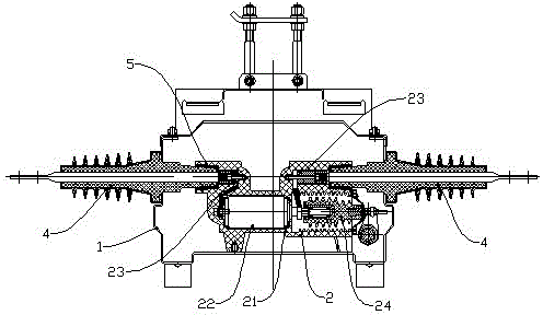
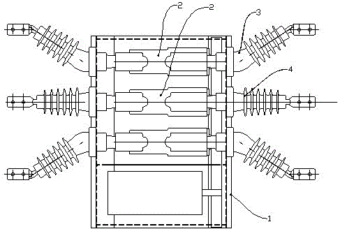
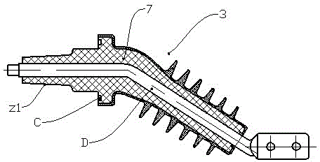
[0016] Such as figure 1 , figure 2 As shown, the vacuum switch on the metal-enclosed solid insulating column includes a metal box 1, and three-phase poles 2 are arranged side by side in the box 1; the poles include an insulating cylinder 21, which is sealed in the insulating cylinder The vacuum interrupter 22, the outlet conductor 23 located in the insulating cylinder and respectively connected to the moving contact and the static contact of the vacuum interrupter, and the insulating pull rod 24 located in the inner cavity of the insulating cylinder to drive the moving contact; Two-phase bent outlet sleeves 3 and one phase straight outlet sleeve 4 are respectively installed on the front and rear wall panels of the box body 1; One end of the straight outlet sleeve 3 and the bent outlet sleeve 4 is located in the box and connected to the end of the pole, and the other end of the straight outlet sleeve 3 and the bent outlet sleeve 4 is located in the box On the outer side of t...


PUM


Abstract

The invention relates to a metal closed solid insulation pole-mounted vacuum switch. The metal closed solid insulation pole-mounted vacuum switch comprises a box body and three phase poles. A front wall plate and a rear wall plate of the box body are respectively provided with two phase bent outgoing line casing pipes and a phase straight outgoing line casing pipe. Each straight outgoing line casing pipe and each bent outgoing line casing pipe are respectively composed of an insulation sleeve and a conductive rod located at the center of the insulation sleeve. One end of each straight outgoing line casing pipe and one end of each bent outgoing line casing pipe are located in the box body and connected with the end portions of the poles. The other end of each straight outgoing line casing pipe and the other end of each bent outgoing line casing pipe are located on the outer sides of the wall plates of the box body. The middle of the straight outgoing line casing pipes and the middle of the bent outgoing line casing pipes are fixedly installed on the wall plates of the box body. The straight outgoing line casing pipes are connected with the phase pole in the middle. The center lines of the straight outgoing line casing pipes are straight. The bent outgoing line casing pipes are connected with two phase poles on the two sides, and the center lines located on the outer side portions of the box body are bent towards the direction away from the straight outgoing line casing pipes. According to the metal closed solid insulation pole-mounted vacuum switch, high insulation capacity is guaranteed, the environmental problem caused by SF6 gas insulation is solved, and the requirement for air tightness of the box body is reduced.

Description

technical field [0001] The invention relates to a power distribution switchgear in a power system, in particular to a metal-enclosed vacuum switch on a solid insulating post. Background technique [0002] In the distribution network, the overhead line is to install the switch on the pole. This type of switch is called a switch on the pole. At present, a variety of switches on the pole are used in the distribution network. With the development of power systems and the improvement of power supply reliability, the full insulation of overhead lines is a development trend. At present, miniaturized vacuum switches with metal sealing are being widely promoted and used. However, the existing small metal sealing Due to the small internal space of the vacuum switch on the column, SF6 gas is used as the insulating medium to enhance the internal insulation strength, which puts forward higher requirements on the sealing of the metal shell, so it is prone to insulation failure caused by S...

Claims


Application Information

Patent Timeline
Patent Type & Authority Applications(China)
IPC IPC(8): H01H33/66
Inventor 文化宾张明志王毅邹积岩廖敏夫段雄英
Owner 北京交通大学长三角研究院
Why Eureka
Try Eureka