Quadrupole permanent magnet synchronous motor rotor
A technology for permanent magnet synchronous motors and rotors, applied to synchronous machine parts, magnetic circuit rotating parts, magnetic circuit shape/style/structure, etc., can solve the problems of low welding strength between the shaft and the iron core and cannot meet the overall performance, and achieve Guarantee the strength, guarantee the effect of operation, and overcome the effect of risk
- Summary
- Abstract
- Description
- Claims
- Application Information
AI Technical Summary
Problems solved by technology
Method used
Image

Examples
Embodiment
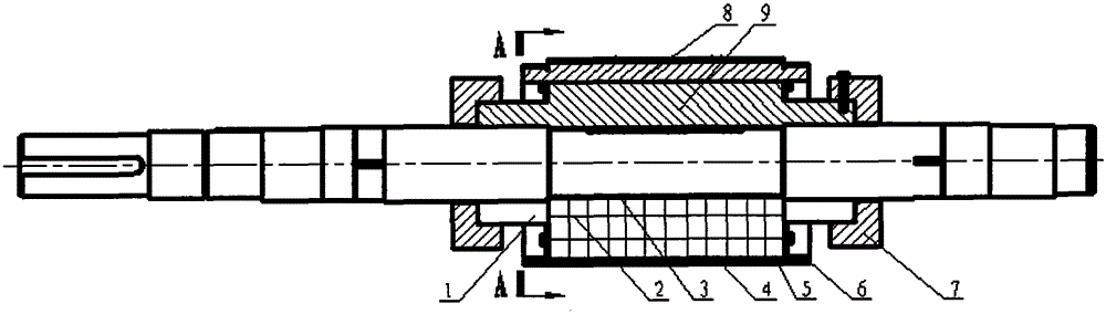
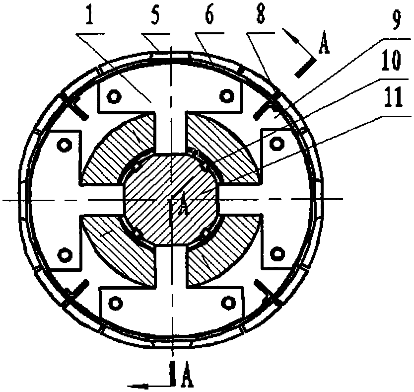
[0023] A kind of quadrupole permanent magnet synchronous motor rotor of the present invention, as figure 1 , 2 As shown, it includes a rotating shaft 11, a key 10, an iron core 9, a magnetic steel 2, a non-magnetic material insulating baffle 1, a collar 6, a copper sheet 8, a slot wedge 5 and a hoop 7;
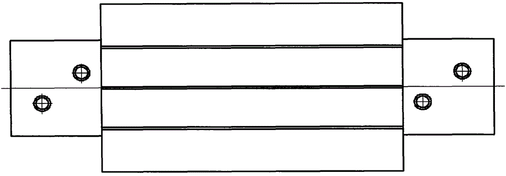
[0024] Such as Figure 5 As shown, an annular groove is processed in the middle section of the rotating shaft 11, and four axially slotted and circumferentially evenly distributed key grooves are processed on the annular groove, and two rows of eight circumferentially evenly distributed misplaced threaded holes are processed on the side walls of the rotating shaft 11 at both ends of the annular groove. ;
[0025] Such as image 3 , 4 As shown, the center of the core 9 is a circular cylinder with an inner diameter and a length matching the annular groove of the rotating shaft 11, which is cut into four fan-shaped sub-pieces with the same structure. The outer wall of each fa...
PUM
 Abstract
Description
Claims
Application Information
 - Generate Ideas
- Intellectual Property
- Life Sciences
- Materials
- Tech Scout
- Unparalleled Data Quality
- Higher Quality Content
- 60% Fewer Hallucinations
Browse by: Latest US Patents, China's latest patents, Technical Efficacy Thesaurus, Application Domain, Technology Topic, Popular Technical Reports.
© 2025 PatSnap. All rights reserved.Legal|Privacy policy|Modern Slavery Act Transparency Statement|Sitemap|About US| Contact US: help@patsnap.com