
Anodizing device, continuous anodizing device, and film forming method

A technology of anodic oxidation and counter electrode, which is applied in the direction of anodic oxidation, electrolytic coating, surface reaction electrolytic coating, etc., and can solve problems such as high cost

Inactive Publication Date: 2014-02-26
FUJIFILM CORP
View PDF5 Cites 5 Cited by
  • Summary
  • Abstract
  • Description
  • Claims
  • Application Information

AI Technical Summary

Problems solved by technology

Therefore, the valve metals need to be replaced frequently due to the progressive increase in contact resistance, but this is not feasible due to the high cost of those materials

Method used


Image

  • Anodizing device, continuous anodizing device, and film forming method
  • Anodizing device, continuous anodizing device, and film forming method
  • Anodizing device, continuous anodizing device, and film forming method

Examples


Embodiment Construction

[0097] Hereinafter, the anodizing apparatus, continuous anodizing apparatus, and film forming method of the present invention will be described in detail by using the drawings.

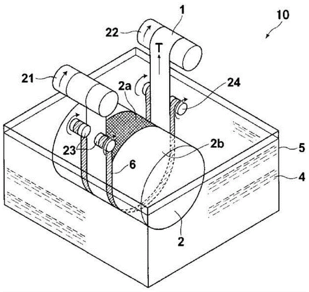
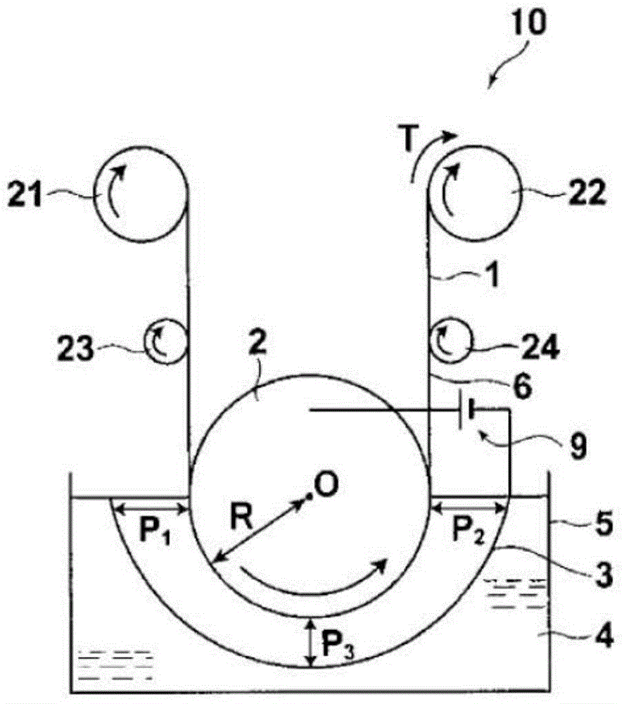
[0098] figure 1 is a schematic perspective view showing an anodizing apparatus of an embodiment for achieving the first object of the present invention, and figure 2 is used to achieve figure 1 A schematic cross-sectional view of the anodizing apparatus of an embodiment of the first object is shown.

[0099] Hereinafter, a general anodizing apparatus for achieving the first to fourth objects of the present invention will be described.

[0100] like figure 1 and figure 2 As shown, the anodizing device 10 of the present invention has: a power supply drum 2, which closely contacts and supports a belt made of anodizable metal or a composite conductive metal foil (at least one surface of which is composed of anodizable metal) Fabricated strip 1 (hereinafter, also referred to simply as "ribbon 1"), a...


PUM

PropertyMeasurementUnit
thicknessaaaaaaaaaa
thicknessaaaaaaaaaa
thicknessaaaaaaaaaa

Abstract

An anodizing device has: a power supply drum that supports, in close contact therewith, a belt-like object consisting of an anodizable metal or consisting of a composite conductive metal foil that is a metal anodizable at least on one side surface thereof and has at least a part configured with a conductive material, to which the belt-like object is closely attached; an opposing electrode provided facing the power supply drum; an electrolysis tank filled with an electrolyte, into which part of the power supply drum supporting the belt-like object in close contact therewith and the opposing electrode are immersed; a protection member formed of a non-conductive material, by which the lateral direction end portions of the belt-like object supported by the power supply drum in close contact therewith and a portion of the power supply drum, to which the belt-like object is not closely attached, are covered and protected from the electrolyte; and a driving unit for making the belt-like object closely attached to the power supply drum and the protection member travel concurrently in the electrolyte in synchronization with the circumferential speed of the power supply drum. If tensile force per unit width applied to the belt-like object wound on the power supply drum is denoted by T (N / m) and the radius of the power supply drum is denoted by R (m), the value of the tensile force (T) per unit width applied to the belt-like object that is made to travel concurrently in the electrolyte is 1000*R or more.

Description

technical field [0001] The present invention relates to an anodizing apparatus, a continuous anodizing apparatus, and a film-forming method suitable for producing semiconductor elements usefully utilized in semiconductor devices such as solar cells, thin-film transistor circuits and displays (image display devices), and electrodes of electrolytic capacitors the substrate. Background technique [0002] In view of the lightness and flexibility of the substrate, a thin-film solar cell using a substrate made of metal has the possibility of being used in various applications compared with a thin-film solar cell using a glass substrate. In addition, since a substrate made of metal can withstand a high-temperature process, photoelectric conversion characteristics are improved, and thus a highly efficient solar cell can be expected. [0003] In a solar cell module, solar cells are integrated by being connected to each other in series on the same substrate, thereby improving module ...

Claims


Application Information

Patent Timeline
Patent Type & Authority Applications(China)
IPC IPC(8): C25D11/00C25D17/00
CPCC25D11/022C25D7/0614C25D11/04C25D11/005C25D11/045
Inventor 祐谷重徳佐藤圭吾垣内良蔵
Owner FUJIFILM CORP
Learn More