Finned tube heat exchanger

A heat exchanger and finned tube technology, which is applied in the field of finned tube heat exchangers, can solve the problem of unequal heat transfer performance of heat exchangers, and achieve the effect of improving heat transfer performance

Active Publication Date: 2015-12-23
PANASONIC CORP
View PDF5 Cites 0 Cited by
  • Summary
  • Abstract
  • Description
  • Claims
  • Application Information

AI Technical Summary

Problems solved by technology

However, in the conventional heat exchanger configured in this way, it is impossible to obtain the effect of the airflow front effect produced by the fins formed by cutting a part of the flat plate material as used in normal heat exchange. As a result of the heat transfer promotion effect, etc., there is a problem that the heat transfer performance of the heat exchanger is not as high as expected

Method used


Image

  • Finned tube heat exchanger
  • Finned tube heat exchanger
  • Finned tube heat exchanger

Examples


Embodiment approach 1

[0058] Next, the fin-tube heat exchanger according to Embodiment 1 of the present invention will be described with reference to the drawings.

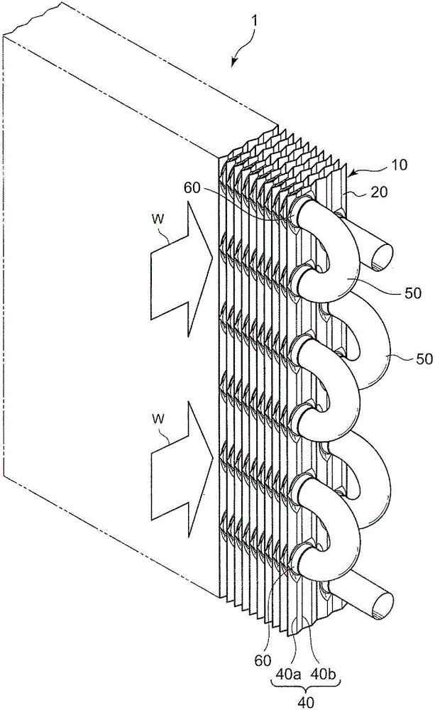
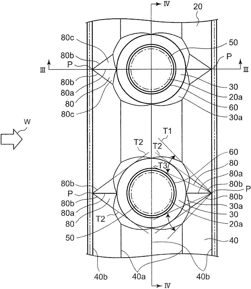
[0059] figure 1 It is a perspective view showing the basic mechanism of the fin-tube heat exchanger according to Embodiment 1 of the present invention. figure 2 will be figure 1 A part of the heat transfer fins of the illustrated fin-and-tube heat exchanger is enlarged, and a front view is shown of the laminated surface which is the front surface of the heat transfer fins.

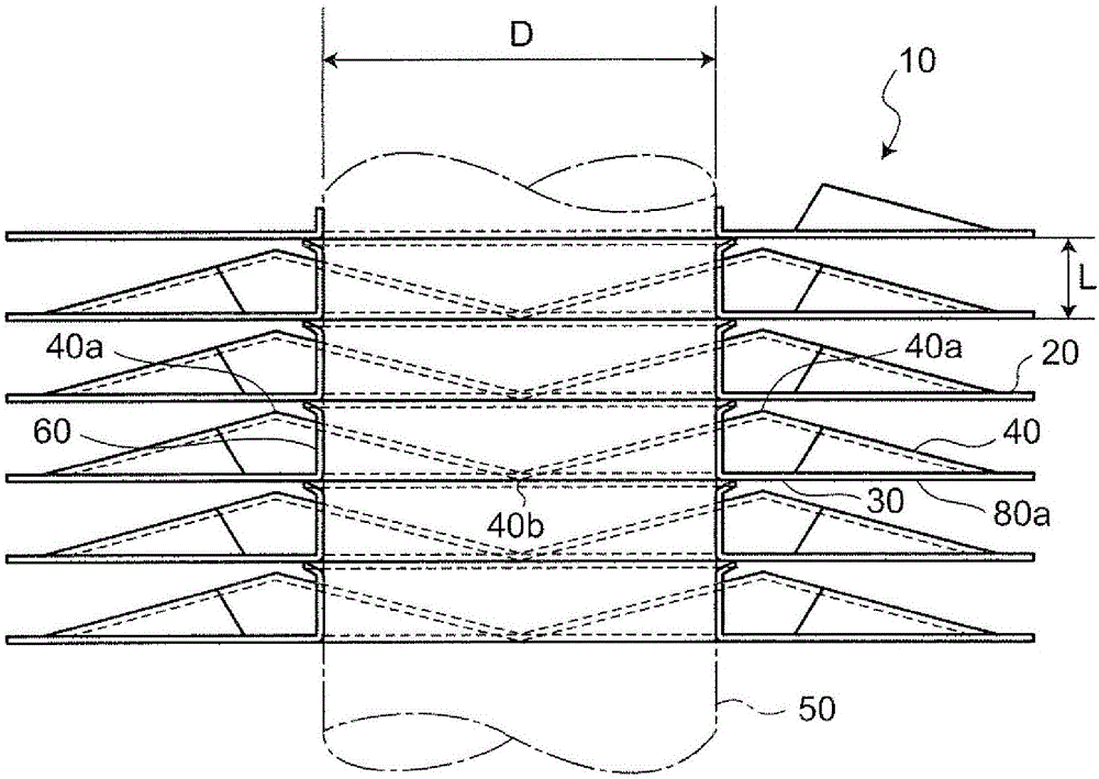
[0060] Such as figure 1 As shown, in the fin-tube heat exchanger 1 , a plurality of heat transfer fins 20 having the same shape are stacked in parallel with a certain interval L (stacked state) to constitute the heat exchange block 10 . In Embodiment 1, the respective heat transfer fins 20 are arranged (stacked) in a row with an interval L of 1.5 mm. The interval L at which each heat transfer fin 20 is arranged can be appropriately changed according to the ...

Embodiment approach 2

[0087] A finned tube heat exchanger according to Embodiment 2 of the present invention will be described with reference to the drawings.

[0088] Image 6 It is a front view showing the laminated surface of the heat transfer fins 20A in the fin-tube heat exchanger according to the second embodiment. Such as Image 6 As shown, a flat seat portion 30 is formed in a ring shape around a fin collar 60 , and a raised portion (peak) 70 is formed around the seat portion 30 .

[0089] In the heat transfer fin 20A of Embodiment 2, wedge-shaped recesses 80 are formed on both sides of the fin collar 60 , both the windward side and the leeward side, as in the above-mentioned Embodiment 1 . As a result, in the heat transfer fin 20A, a part of the raised portion (peak portion) 70 formed around the seat portion 30 is formed so that the upwind side and the leeward side are notched (there are voids). As a result, in the fin-and-tube heat exchanger according to Embodiment 2, the airflow flowi...

Embodiment approach 3

[0092] Embodiment 3 of the fin-tube heat exchanger of the present invention will be described with reference to the drawings.

[0093] Figure 7 It is a front view showing the laminated surface of the heat transfer fins 20B of the fin-tube heat exchanger according to the third embodiment. Such as Figure 7 As shown, an elliptical seat portion 30 having a flat surface is formed around the fin collar 60 , and a standing portion (peak portion) 70 is formed around the seat portion 30 .

[0094]In the heat transfer fin 20B according to the third embodiment, wedge-shaped recesses 80 are formed on both the windward side and the leeward side of the fin collar 60 as in the above-mentioned first embodiment. As a result, in the heat transfer fin 20B, a part of the raised portion (peak portion) 70 formed around the seat portion 30 is missing on the windward side and the leeward side (there is a void portion). As a result, in the fin-and-tube heat exchanger according to Embodiment 3, th...


PUM


Abstract

Provided is a fin tube heat exchanger in which multiple stacked fins are formed into a particular shape so as to make the air flow between the fins smoother and which exhibits excellent heat transfer performance by increasing the ridge lines that are the lines of intersection between surfaces in order to enhance the heat transfer performance between the fins and the air flow. A fin tube heat exchanger wherein: stacked heat-transfer fins each have a wedge-shaped dent (80) on the upstream wind side and the downstream wind side of a fin collar (60); the dent (80) is configured from a first ridge line (80a) extending in the column direction in the upstream wind side and downstream wind side of the fin collar (60), and two second ridge lines (80b) which are arranged in the shape of a V and which derive from the vertex (P) of the first ridge line (80a) and a ridge line (40b) on the valley side extending in the step direction; and two V-shaped slanted planes are formed by means of the first ridge line (80a) and the second ridge lines (80b).

Description

technical field [0001] The present invention relates to air conditioners such as indoor air conditioners, box-type air conditioners, and automobile air conditioners, heat pump water heaters, refrigerators and freezers, etc. A finned tube heat exchanger that transfers heat between flowing air and other gases and fluids such as water or refrigerant flowing in the heat transfer tubes. Background technique [0002] The finned tube heat exchanger is usually a finned and tubed heat exchanger composed of a plurality of laminated flat fins and heat transfer tubes. Figure 10 It is a perspective view showing a conventional heat exchanger. Figure 11 yes means Figure 10 Front view of part of the fin shown. Such as Figure 10 with Figure 11 As shown, the conventional fin-and-tube heat exchanger 101 includes: flat-plate fins 110 stacked in parallel at a certain interval; and heat transfer tubes 130 inserted through the stacked fins 110 . A cylindrical fin collar 116 standing vertic...

Claims


Application Information

Patent Timeline
Patent Type & Authority Patents(China)
IPC IPC(8): F28F1/32
CPCF28F1/32F28D1/0477F28F2215/10
Inventor 横山昭一
Owner PANASONIC CORP
Why Eureka
Try Eureka