Ball joint locking method and device

A technology of locking device and ball joint, which is applied in the field of medical equipment, can solve problems such as the switch is not so easy, affects the performance of use, and the positioning deviation of the end, so as to reduce the design cost, respond quickly, and avoid the increase of manufacturing cost.

Active Publication Date: 2014-03-05
SHENZHEN INST OF ADVANCED TECH CHINESE ACAD OF SCI
View PDF6 Cites 39 Cited by
  • Summary
  • Abstract
  • Description
  • Claims
  • Application Information

AI Technical Summary

Problems solved by technology

Although the above-mentioned device can quickly switch between locking and loosening, it has too many parts and a complicated structure. If it is to achieve precise control, it also needs accessories such as force or displacement sensors; Or if many of the robot products are used at the same time, each joint needs to be equipped with a motor for locking, which makes the cost of the product very high, and it is not so easy to control the switches of several motors at the same time; The obvious shortcoming is that it cannot provide a certain preload to the ball joint, and there may be a gap in the ball joint in a relaxed state, which will cause a large deviation in the positioning of the end and affect the performance

Method used


Image

  • Ball joint locking method and device
  • Ball joint locking method and device
  • Ball joint locking method and device

Examples


Embodiment Construction

[0025] In order to make the object, technical solution and advantages of the present invention clearer, the present invention will be further described in detail below in conjunction with the accompanying drawings and embodiments. It should be understood that the specific embodiments described here are only used to explain the present invention, not to limit the present invention.

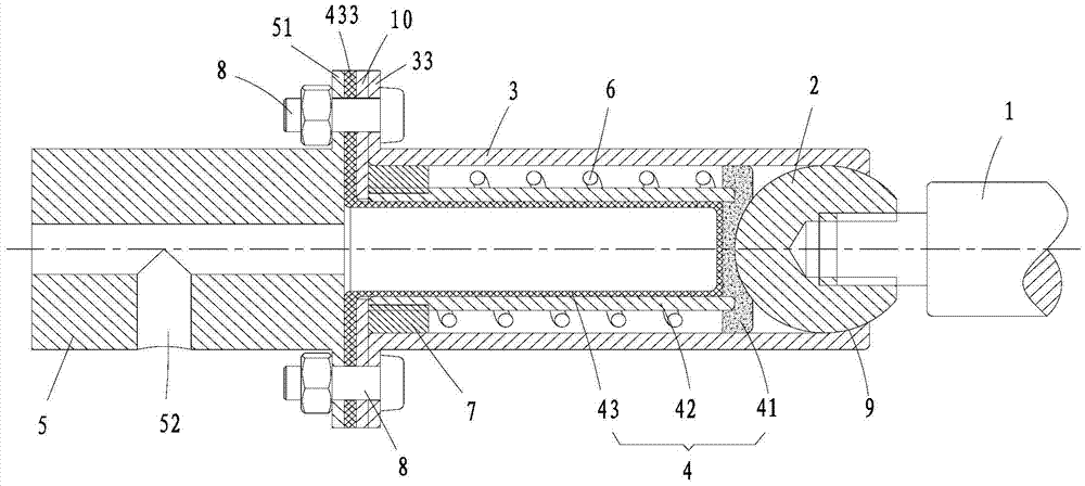
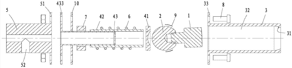
[0026]The present invention firstly provides a ball joint locking method, so that the ball joint can be locked at any angle, which is that the ball head on the ball joint is set in a connecting sleeve that can be locked or loosened. The head is hinged with the connecting sleeve, so that the ball head can freely rotate in the relaxed state in the cavity matched with the connecting sleeve; at the corresponding position on the outer circumference of the ball head, a pressing component that can be abutted by the ball head is also provided , and the pressing component is connected to the hydraulic syste...


PUM


Abstract

The invention provides a ball joint locking method and a locking device designed according to the method. A ball head of a ball joint is sleeved with a connecting sleeve which can be movably locked with the ball head or be in a release state with the ball head. An abutting assembly connected with a hydraulic system is arranged in a position corresponding to a matching position of the ball head and the connecting sleeve at locking time. Under the action of pressure oil provided by the hydraulic system, the abutting assembly is forced to instantly press the outer surface of the ball head and enables the ball head to abut against the position matched with the connecting sleeve at the same time, so that the abutting assembly and the connecting sleeve lock the ball head in a multipoint mode. When pressure is released, the abutting assembly and the connecting sleeve can restore to original positions automatically, so that the locking state and the release state of the ball joint can be switched quickly. According to the ball joint locking method and the locking device, the characteristics that the hydraulic system is small in inertia and quick in response are fully utilized, so that that the device have the advantages of being simple in structure, reliable in locking, and good in effect, and can ensure rigid connection and bear certain load moment at the same time. Moreover, locking devices can be connected in series through the same oil path for utilization in one product.

Description

technical field [0001] The invention relates to the field of medical devices, in particular to a ball joint locking method and device for a man-machine interactive (also called passive) mechanical arm and a robot. Background technique [0002] The ball joint mechanism is a mechanism commonly used in the medical device industry. It has three degrees of freedom of rotation, so the flexibility is very good. It is a very good choice for the man-machine cooperation manipulator that requires high flexibility. Due to the particularity of the processing technology of the ball joint and its own structural characteristics, the ball The problem of joint locking is not so simple. In general applications, the friction between the ball head and the ball tile is increased by manually tightening the screws to achieve locking, and automatic control cannot be realized. [0003] The medical devices (robot arms) used in surgical operations and minimally invasive operations require not only the...

Claims


Application Information

Patent Timeline
Patent Type & Authority Applications(China)
IPC IPC(8): A61G13/10B25J17/00B25J19/00F16C11/10
Inventor 张朋胡颖侯西龙张建伟朱丽
Owner SHENZHEN INST OF ADVANCED TECH CHINESE ACAD OF SCI
Why Eureka
Try Eureka