Adaptive deformation-resistant supporting fixture

An anti-deformation and self-adaptive technology, applied in the direction of clamping, supporting, manufacturing tools, etc., can solve the problems of low relative rigidity, uneven clamping force of parts, low processing precision of parts, etc., and achieve enhanced structural rigidity and stable clamping High performance and high machining accuracy

Inactive Publication Date: 2014-03-05
SHENYANG LIMING AERO-ENGINE GROUP CORPORATION
View PDF5 Cites 16 Cited by
  • Summary
  • Abstract
  • Description
  • Claims
  • Application Information

AI Technical Summary

Problems solved by technology

[0002] Compressor disks, turbine disks and blisks are important components of aero-engines, and they are classified as weakly rigid disk parts. The relative stiffness and strength of these parts are relatively low, and the processing technology is poor, especially for the shape of parts. In the case of high requirements for bit error and dimensional error, the parts are very sensitive to vibration, cutting force and cutting temperature during processing. A little carelessness will deform the part, and it is difficult to guarantee the processing accuracy.
[0003] In order to avoid the deformation of the parts during processing, the clamping and fixing of the parts is very important. At this stage, the auxiliary support of the adjustable screw with the head i

Method used


Image

  • Adaptive deformation-resistant supporting fixture
  • Adaptive deformation-resistant supporting fixture

Examples


Embodiment Construction

[0019] The present invention will be further described in detail below in conjunction with the accompanying drawings and specific embodiments.

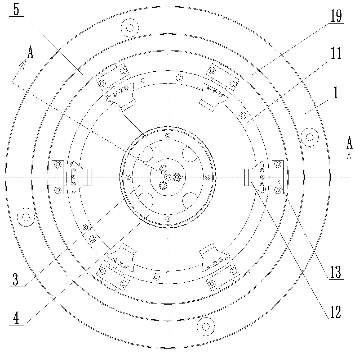
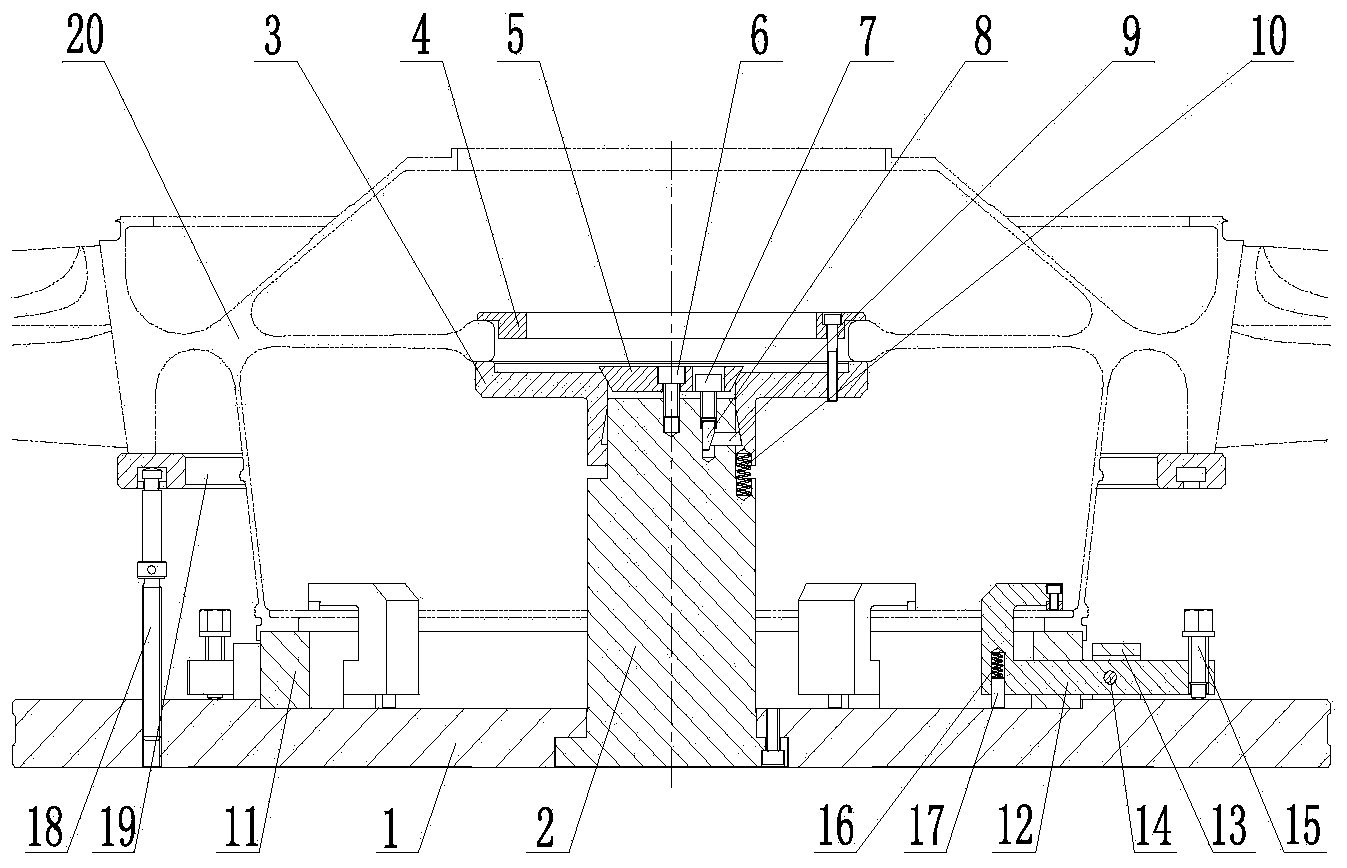
[0020] Such as figure 1 , 2 As shown, an adaptive support anti-deformation fixture includes a base 1, a central support 2, a central support plate 3, a first central pressure plate 4, a second central pressure plate 5, a positioning ring 11 and a circumferential pressure plate 12. The base 1 is set in a disc-shaped structure, the central support 2 is fixed in the center of the base 1, the central support plate 3 is set on the upper end of the central support 2, and the central support plate 3 and the central support 2 in the direction of the set There are four thrust springs 10 evenly arranged therebetween;

[0021] A through hole is provided in the middle of the center support plate 3, and the second center pressure plate 5 contacts and cooperates with the center support plate 3 through the through hole. A first locking bolt 6 is ...


PUM


Abstract

The invention provides an adaptive deformation-resistant supporting fixture, and belongs to the technical field of manufacture of parts of aero-engines. A center support of the adaptive deformation-resistant supporting fixture is fixedly arranged in the center of a base; a center supporting plate is sleeved at the upper end of the center support; a thrust spring is arranged between the center supporting plate and the center support; a second center pressing plate is in contact fit with the center supporting plate, and a contact surface is an inclined surface; the second center pressing plate is connected with the center support through a first locking bolt; a second locking bolt is arranged on the center support and faces the second center pressing plate; a vertical lifting pin and a transverse lifting pin are arranged in the center support and at the second locking bolt; the transverse lifting pin corresponds to the inner wall of a sleeving section of the center supporting plate; a first center pressing plate is arranged above the second center pressing plate; a positioning ring is positioned on the base and on the outer side of the center support; one end of a peripheral pressing plate is positioned above the positioning ring; the other end of the peripheral pressing plate is matched with the base through a compression bolt; the peripheral pressing plate is provided with a rotating shaft; the rotating shaft is arranged on the base through a fixing block; and a supporting ring is arranged on the outer side of the positioning ring.

Description

technical field [0001] The invention belongs to the technical field of manufacturing aero-engine parts, in particular to an adaptive support anti-deformation fixture. Background technique [0002] Compressor disks, turbine disks and blisks are important components of aero-engines, and they are classified as weakly rigid disk parts. The relative stiffness and strength of these parts are relatively low, and the processing technology is poor, especially for the shape of parts. In the case of high requirements for bit error and dimensional error, the parts are very sensitive to vibration, cutting force and cutting temperature during processing. A little carelessness will deform the part, and it is difficult to guarantee the processing accuracy. [0003] In order to avoid the deformation of the parts during processing, the clamping and fixing of the parts is very important. At this stage, the auxiliary support of the adjustable screw with the head is generally used for the clampi...

Claims


Application Information

Patent Timeline
IPC IPC(8): B23Q3/00
CPCB23Q3/00
Inventor 张娟彭会文杜媛媛阚敏祖峰
Owner SHENYANG LIMING AERO-ENGINE GROUP CORPORATION
Why Eureka
Try Eureka