A gas pipeline liquid metal sealing valve for high temperature environment

A gas pipeline, liquid metal technology, applied in the direction of lift valve, valve details, valve device, etc., can solve the problems of easy anastomosis, poor sealing, etc., to achieve low volatility, large specific gravity, and solve the effect of absolute sealing difficulty.

Active Publication Date: 2016-06-01
XIXIA LONGCHENG SPECIAL MATERIALS CO LTD
View PDF8 Cites 0 Cited by
  • Summary
  • Abstract
  • Description
  • Claims
  • Application Information

AI Technical Summary

Problems solved by technology

However, the above-mentioned balanced high-pressure globe valve belongs to the category of two hard plane contact seals. Under high temperature and high pressure, it is still easy to fit loosely and reduce the sealing performance. Therefore, further improvement is needed.

Method used


Image

  • A gas pipeline liquid metal sealing valve for high temperature environment
  • A gas pipeline liquid metal sealing valve for high temperature environment
  • A gas pipeline liquid metal sealing valve for high temperature environment

Examples


Embodiment 1

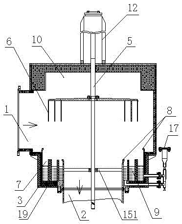
[0030] like figure 1 As shown, a gas pipeline liquid metal sealing valve for high temperature environment includes a valve body 3 provided with an air inlet 1 and an air outlet 2, the valve body 3 is pierced with a valve stem 5, and the upper part of the valve stem 5 is Connect the valve rod driving device 12, the valve rod driving device 12 is an air cylinder or hydraulic cylinder, the lower part of the valve rod 5 is connected to the isolation cover structure, and the isolation cover structure includes a three-layer isolation cover unit 6, the valve body 3 There are three groups of sealing groove units 7 arranged at the bottom, liquid metal 9 is injected into the sealing groove units 7, an anti-splash ring 8 is arranged at the upper end of the sealing groove units 7, a groove 10 is arranged inside the valve body 3, and the The size of the groove 10 is larger than the maximum size of the isolation cover structure; the valve body 3 is provided with a guide assembly 151 for the...

Embodiment 2

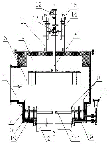
[0039] like figure 2 As shown, a gas pipeline liquid metal sealing valve for high temperature environment includes a valve body 3 provided with an air inlet 1 and an air outlet 2, the valve body 3 is pierced with a valve stem 5, and the upper part of the valve stem 5 is Connect the valve stem driving device 12, the lower part of the valve stem 5 is connected to the isolation cover structure, the isolation cover structure includes a three-layer isolation cover unit 6, and three sets of sealing groove units 7 are arranged at the bottom of the valve body 3, and the sealing The tank unit 7 is filled with liquid metal 9, the upper end of the sealing tank unit 7 is provided with a splash guard ring 8, and the inner side of the valve body 3 is provided with a groove 10, and the size of the groove 10 is larger than the maximum size of the isolation cover structure . The valve stem driving device 12 is arranged on the sleeve 11 on the valve body 3, the output end of the valve stem dr...

Embodiment 3

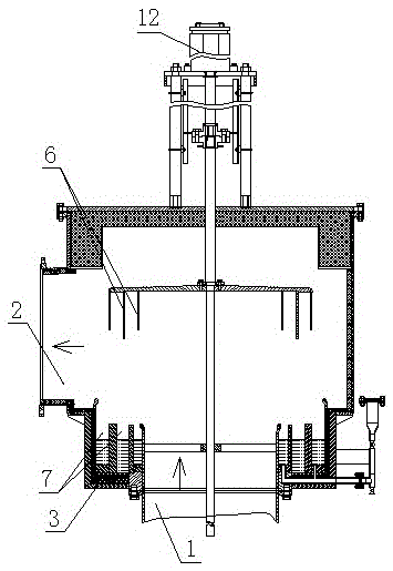
[0042] like image 3 As shown, a gas pipeline liquid metal sealing valve for high-temperature environments differs from Embodiment 1 or 2 in that: the sealing groove units 7 are arranged in random order, and the vertical size of the isolation cover unit 6 is adapted to the sealing groove unit 7, the air inlet 1 is in the lower position.


PUM


Abstract

The invention discloses an improved air pipe liquid metal sealing valve for the high temperature environment. The improved air pipe liquid metal sealing valve comprises a valve body with an air inlet and an air outlet, an isolation hood structure connected with a motion mechanism is arranged in the valve body, the isolation hood structure comprises at least two layers of isolation hood units, sealing groove units in the corresponding number are arranged at the bottom of the valve body, the sealing groove units are filled with liquid metal and arranged in a stagger mode, and the vertical sizes of the isolation hood units are matched with the heights of the sealing groove units. According to the improved air pipe liquid metal sealing valve, the sealing mode that a plurality of liquid metal seals are selected is used, the technical effect of absolute sealing of the isolation hood units is easily achieved, the isolation stability coefficient is high, the improved air pipe liquid metal sealing valve can be suitable for maintenance even pressure relief situations after air supply is stopped, an internally-formed pressure stabilizing area is used, the good liquid sealing effect is guaranteed, the improved air pipe liquid metal sealing valve is long in using period, few in loss, accurate in control and low in cost, and has the good popularization and use value.

Description

technical field [0001] The invention relates to the technical field of gas valves, in particular to a liquid metal sealing valve for gas pipelines used in high-temperature environments. Background technique [0002] The sealing technology of the on-off control part of the high-temperature gas system pipeline is an urgent problem to be solved in the relevant field at present. The traditional control method generally adopts the disc globe valve. Disc globe valves have a relatively large gap between the disc and the valve body, are prone to wear, and are prone to rust, resulting in poor sealing performance and frequent repairs and replacements, resulting in increased purchase and use costs. In addition, in the existing globe valve, the contact surface between the valve body and the disc is usually set as a large plane, and the two hard planes are in contact with each other to seal. Or impurities accumulate on the plane, resulting in a loose fit between the contact surface and ...

Claims


Application Information

Patent Timeline
Patent Type & Authority Patents(China)
IPC IPC(8): F16K31/12F16K49/00F16K1/32F16K1/46
CPCF16K13/10F16K37/00F16K49/00
Inventor 朱书成黄国团赵家亮吕艳吾
Owner XIXIA LONGCHENG SPECIAL MATERIALS CO LTD
Why Eureka
Try Eureka