Microwave oven

A technology for microwave ovens and air outlets, applied in the field of microwave ovens, can solve problems such as high outer cover temperature, unreasonable air ducts, and many shutters, and achieve the effects of reducing heat dissipation, avoiding burn accidents, and ensuring safety

Active Publication Date: 2014-03-05
MIDEA GRP CO LTD +1
View PDF10 Cites 16 Cited by
  • Summary
  • Abstract
  • Description
  • Claims
  • Application Information

AI Technical Summary

Benefits of technology

This patented technology relieves problems associated with traditional design of an electric wave furnace used within buildings due to its limited ability to efficiently remove excessive thermal energy produced by the device itself without damaging any items or people nearby. By circulating hot air around the devices instead of direct exposure towards them, this helps maintain safe operation while also minimizing overheating issues caused by condensation. Additionally, there may include various fume evacuations systems to help reduce odors emitted from the apparatus' exterior. Overall, these technical improvements enhance the functionality and performance of the electric wavelength range (EW) microswitch boiler).

Problems solved by technology

This patented technical problem addressed in this patents relates to improving the efficiency at cooling down microwaves while maintaining good thermal performance for other functions such as food preparations.

Method used


Image

  • Microwave oven
  • Microwave oven
  • Microwave oven

Examples


Embodiment Construction

[0042] In order to understand the above-mentioned purpose, features and advantages of the present invention more clearly, the present invention will be further described in detail below in conjunction with the accompanying drawings and specific embodiments. It should be noted that, in the case of no conflict, the embodiments of the present application and the features in the embodiments can be combined with each other.

[0043] In the following description, many specific details are set forth in order to fully understand the present invention. However, the present invention can also be implemented in other ways than described here. Therefore, the protection scope of the present invention is not limited by the specific implementation disclosed below. Example limitations.

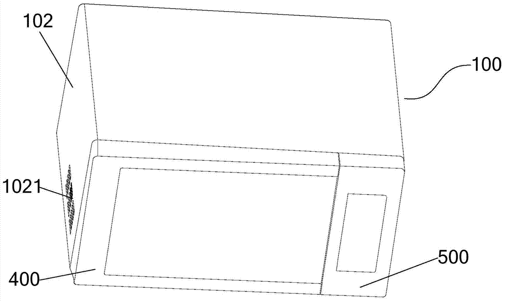
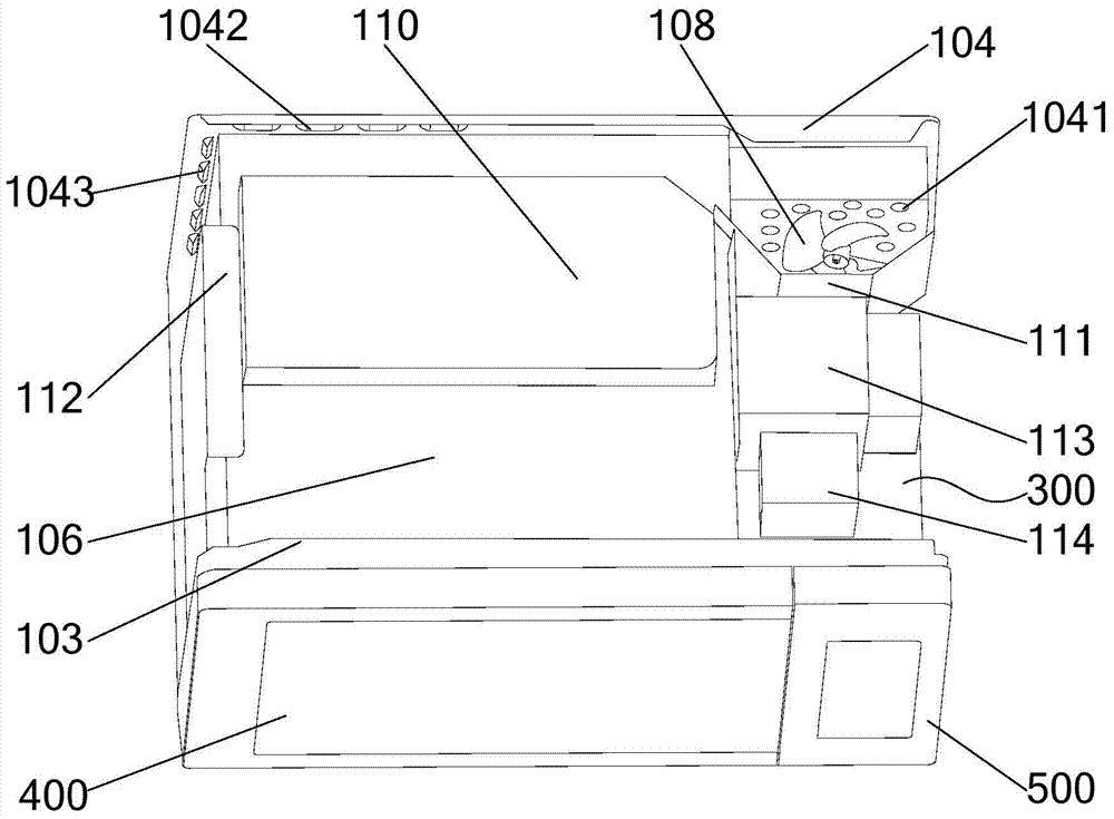
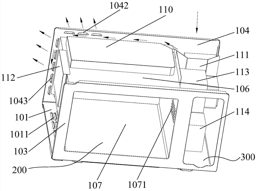
[0044] Refer to the attached figure 1 to attach Figure 8 The microwave oven 100 provided according to some embodiments of the present invention is described, and the arrows in the figure indicate the flow ...


PUM


Abstract

The invention provides a microwave oven which comprises a microwave oven shell defined by a bottom plate, an outer case, a front plate and a back plate, wherein an electrical room and a hollow cooking cavity are arranged in the shell; the hollow cooking cavity is defined by a top plate, the front plate, a U-shaped plate and the back plate, and is open at one end; the shell is provided with an air inlet and an air outlet; a fan is arranged in a manner of being dead against the air inlet; a heating pipe hood covering heating elements is arranged on the top plate; a first air channel is formed among a back wall of the heating pipe hood, the back plate and the outer case; a second air channel is formed among a front wall of the heating pipe hood, the front plate and the outer case; an air inlet hole is formed in a side plate of the U-shaped plate, and an air outlet hole is formed in the other side plate of the U-shaped plate; the air inlet hole, the air outlet hole and the cavity form a third air channel; in the electrical room, an air guide plate is arranged at the air outlet of the fan; the air guide plate can guide cold air blown out by the fan to pass through the first, second and third air channels respectively, and flow out via the air outlet. The microwave oven provided by the invention has the advantages that the temperature of the surface of the microwave oven can be effectively reduced, and the safety of the microwave oven is improved.

Description


Claims


Application Information

Patent Timeline
Owner MIDEA GRP CO LTD
Why Eureka
Try Eureka