Sensor circuit

A sensor circuit and sensor technology, applied in instruments, using electric/magnetic devices to transmit sensing components, adjusting electrical variables, etc., can solve the DC operation of amplifiers or buffers with small effective impedance, large effective impedance, and impedance nonlinear characteristics Problems such as point drift can be eliminated to achieve the effect of reducing the overall area and reducing the marginal effect

Active Publication Date: 2014-03-05
AAC ACOUSTIC TECH (SHENZHEN) CO LTD +1
View PDF4 Cites 6 Cited by
  • Summary
  • Abstract
  • Description
  • Claims
  • Application Information

AI Technical Summary

Problems solved by technology

For example, when the sensing voltage signal output by the sensor is large, the effective impedance of the impedance bias circuit is relatively large when the forward large signal is large, and the effective impedance is small when the reverse large signal is large; and , the impedance bias circuit using the current mirror may also cause rectification effect due to parity distortion; the impedance nonlinearity and rectification effect of the above impedance bias circuit may cause the DC operating point of the amplifier or buffer to drift

Method used


Image

  • Sensor circuit
  • Sensor circuit
  • Sensor circuit

Examples


Embodiment Construction

[0023] The following will clearly and completely describe the technical solutions in the embodiments of the present invention with reference to the accompanying drawings in the embodiments of the present invention. Obviously, the described embodiments are only some, not all, embodiments of the present invention. Based on the embodiments of the present invention, all other embodiments obtained by persons of ordinary skill in the art without making creative efforts belong to the protection scope of the present invention.

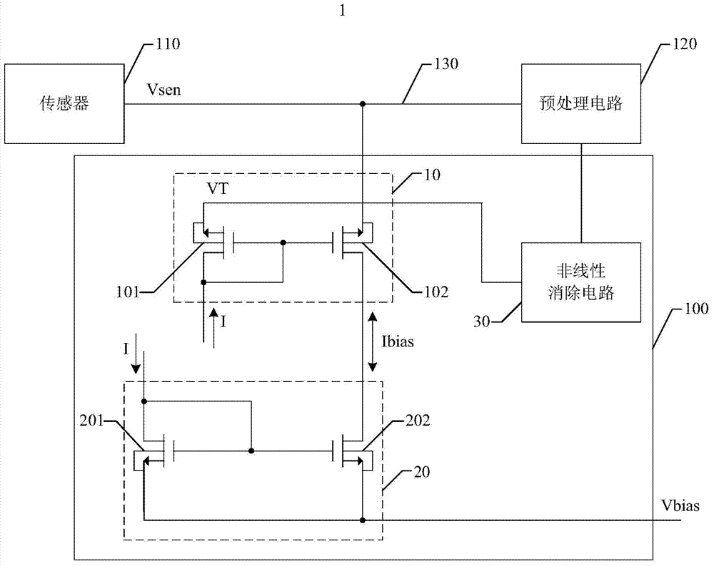
[0024] see figure 1 , which is a schematic diagram of the circuit structure of the first embodiment of the sensor circuit provided by the present invention. The sensor circuit 1 can be, but not limited to, sensor circuits such as accelerometers, gyroscopes, and microphones, and it can be applied to electronic products such as mobile phones, conference phone systems, digital cameras, bluetooth headsets, video phones, and tablet computers. exist figure 1 In th...


PUM


Abstract

The invention provides a sensor circuit which comprises a sensor, a preprocessing circuit and an impedance biasing circuit, wherein the sensor is connected to the preprocessing circuit through an input connection wire. The impedance biasing circuit is connected between the input connection wire and a bias point and comprises a first impedance switching circuit and a second impedance switching circuit. The first impedance switching circuit comprises a first transistor and a second transistor. The first transistor and the second transistor are connected to form a first current mirror. The second impedance switching circuit comprises a third transistor and a fourth transistor. The third transistor and the fourth transistor are connected to form a second current mirror. The second current mirror is connected to the first current mirror in a reverse matching current mirror mode and receives bias voltage supplied by the bias point. The first transistor, the second transistor, the third transistor and the fourth transistor work in a sub-threshold region under the action of the bias voltage.

Description

technical field [0001] The present invention relates to electronic circuit technology and, in particular, to a sensor circuit with self-biased high input impedance. Background technique [0002] With the development of sensing technology, capacitive sensors are widely used in consumer electronic products to implement accelerometers, gyroscopes, microphones, etc. because they can automatically detect and generate corresponding detection signals. Generally, the input terminal of the amplifier (Amplifier) ​​or buffer (Buffer) needs to be biased at the normal operating voltage. The capacitance of the capacitive sensor is generally small, about several pF. Therefore, it can be used at the input terminal of the amplifier or buffer Simply connect a high-resistance resistor, about a giga-ohm range of resistance, but because a high-resistance resistor usually takes up a large device area, the above-mentioned high input impedance implementation method is rarely used in actual circuit ...

Claims


Application Information

Patent Timeline
Patent Type & Authority Applications(China)
IPC IPC(8): G05F3/26G01D5/24
CPCG01D5/24
Inventor 陈晓翔蔡东记
Owner AAC ACOUSTIC TECH (SHENZHEN) CO LTD
Why Eureka
Try Eureka