
Apparatus and method for separating carrier liquid vapor from ink

A gas, pressurized gas technology, applied in the field of equipment and methods for separating carrier liquid vapor from ink, capable of solving problems such as re-dissolution, accumulation, deposition film contamination, etc.

Active Publication Date: 2018-05-04
KATEEVA
View PDF5 Cites 0 Cited by
  • Summary
  • Abstract
  • Description
  • Claims
  • Application Information

AI Technical Summary

Problems solved by technology

Recondensation can cause buildup of unwanted material in equipment
Such buildup on the transfer surface may result in transfer of the carrier liquid to the intended substrate, causing contamination or redissolution of the deposited film

Method used


Image

  • Apparatus and method for separating carrier liquid vapor from ink
  • Apparatus and method for separating carrier liquid vapor from ink
  • Apparatus and method for separating carrier liquid vapor from ink

Examples


Embodiment Construction

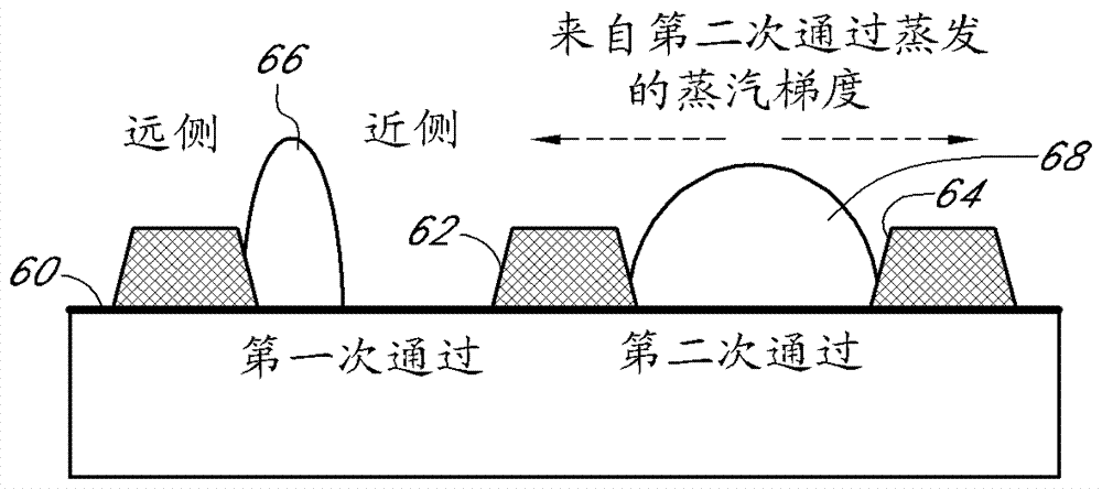
[0057] The present teachings relate to discovering and solving troublesome problems faced by printing with various inks on substrates. The problem involves a phenomenon referred to herein as "stacking". Stacking may occur when a first region of pixels is printed on a substrate and then a second adjacent region is printed on the same substrate. At the interface between these two zones, a row of pixels in the first print zone may experience stacking, that is, ink remains at one end of the pixel bank compared to at the opposite end of the pixel bank. There is more ink that dries this way. As a result, non-uniform pixels are produced. can refer to Figure 1A , 1B and 1C to better understand this phenomenon.

[0058] Figure 1A is a top view of a schematic representation of substrate 40 . The substrate 40 is shown divided into two zones, a first zone 42 and a second zone 44 , the interface of which is a boundary 43 . Pixel banks 48 are shown in the first row of pixel banks 46...


PUM


Abstract

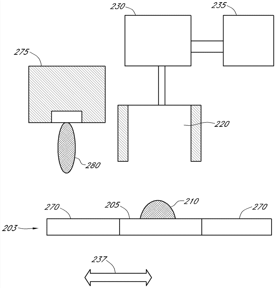
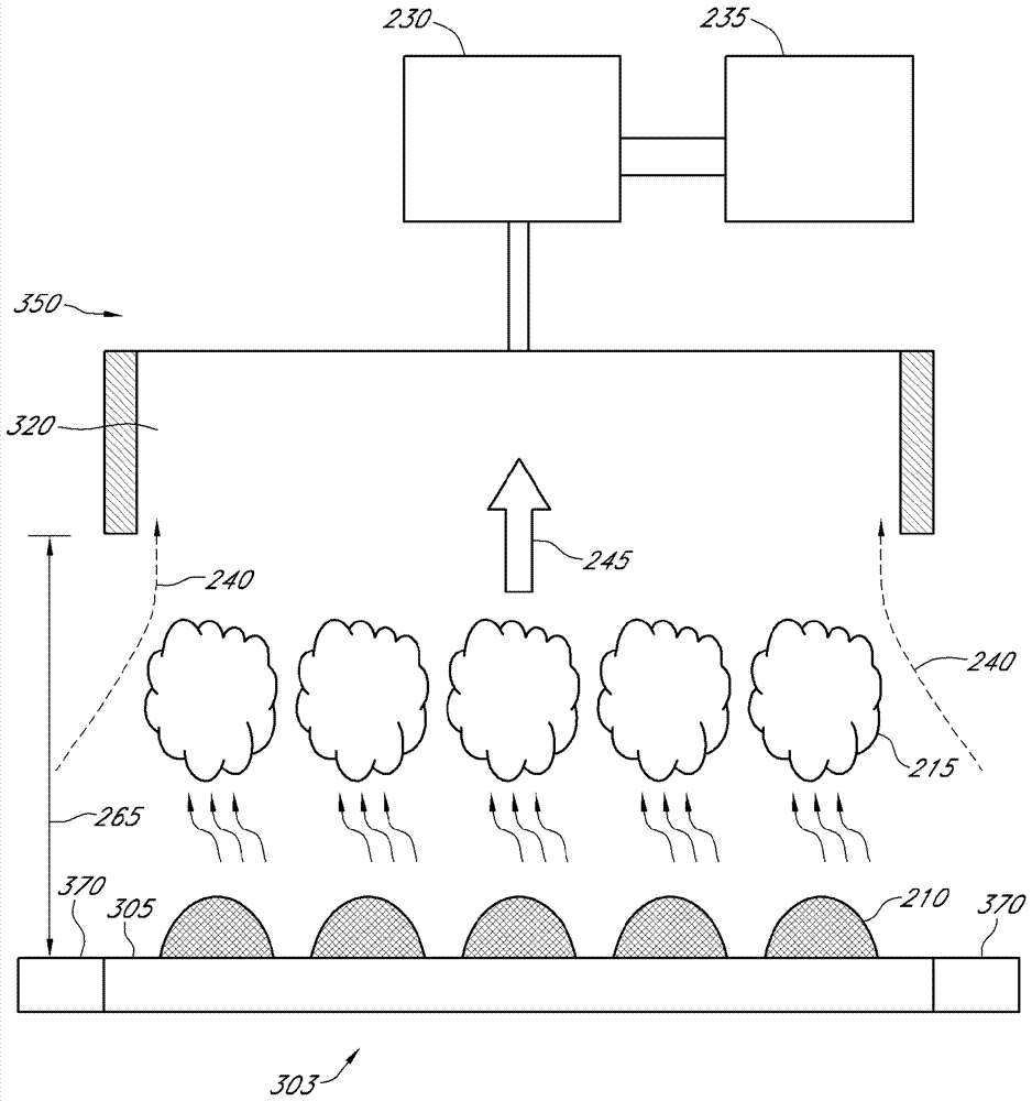
Systems, apparatus, and methods are provided that include or use a chuck, an inkjet printhead, and an air knife to form a film layer on a substrate that has uniform feature sizes and avoids stacking of inkjet inks. In some systems, a gas moving device is used instead of a gas knife. The systems, apparatus and methods can be used to print layers on substrates to be used in organic light emitting devices.

Description

[0001] Cross References to Related Applications [0002] This application claims the benefit of U.S. Provisional Patent Application No. 61 / 504,051, filed July 1, 2011, and U.S. Provisional Patent Application No. 61 / 651,847, filed May 25, 2012, both of which are incorporated by reference in their entirety here. This application also incorporates by reference US Provisional Patent Application No. 61 / 625,659, filed April 17, 2012, in its entirety. technical field [0003] The present teachings relate to methods, apparatus, and systems for separating carrier liquid vapor from ink during printing of ink onto a substrate in the manufacture of various products, such as organic light emitting devices. Background technique [0004] The manufacture of organic light emitting devices (OLEDs) involves high precision to achieve a product that functions properly and meets customer expectations. Printing organic materials onto substrates to form pixels in such devices presents various cha...

Claims


Application Information

Patent Timeline
Patent Type & Authority Patents(China)
IPC IPC(8): H01L51/56H05B33/10
CPCH10K71/135H10K71/441G03F7/2018H10K71/00
Inventor J.陈E.马丁內斯A.S-K.科I.米拉德E.弗伦斯基C.F.马迪甘
Owner KATEEVA
Learn More