Bottle cap assembling device and assembling method

A technology for assembling devices and bottle caps, which is applied in metal processing, metal processing equipment, manufacturing tools, etc., and can solve the problem that the bottle cap assembly cannot be effectively fixed, the scope of application of the bottle cap assembly machine is narrow, and the cap body of the bottle cap assembly is damaged, etc. problems, to achieve the effect of improving work stability, reducing debugging difficulty, and reducing scrap rate

Active Publication Date: 2014-03-12
SICHUAN XINGDA PACKAGING EQUIP MFG
View PDF8 Cites 28 Cited by
  • Summary
  • Abstract
  • Description
  • Claims
  • Application Information

AI Technical Summary

Problems solved by technology

[0005] The upper die head directly presses the bottle cap assembly on the cap body. During the pressing process, the bottle cap assembly cannot be effectively fixed, and the bottle cap assembly is prone to radial movement, which can easily cause the bottle cap assembly to be damaged during pressing. Skew, eventually lead to damage to the cover body of the bottle cap assembly
[0006] In addition, based on the working method

Method used


Image

  • Bottle cap assembling device and assembling method
  • Bottle cap assembling device and assembling method
  • Bottle cap assembling device and assembling method

Examples


Embodiment 1

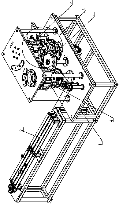
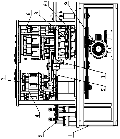
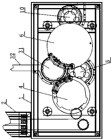
[0068] like figure 1 , figure 2 and image 3 As shown, the bottle cap assembly device includes a frame 1, an outer cap feeding mechanism 2, an inner cap feeding mechanism 3, an auxiliary turret 4, a transfer dial 5 and a pressing turret 6;

[0069] Auxiliary turret 4, transfer dial 5 and pressing turret 6 are rotatably arranged on frame 1, auxiliary turret 4 is provided with suction device 7, and pressing turret 6 is provided with suction device 7 and jacking device 8 , the jacking device 8 is located directly below the suction device 7;

[0070] The outer cover feeding mechanism 2 is arranged on the frame 1 and transports the outer cover to the auxiliary turret 4 so that the outer cover is sucked by the suction device 7 on the auxiliary turret 4;

[0071] The auxiliary turret 4 rotates to transport the outer cover sucked by the suction device 7 to the transfer dial 5;

[0072] The transfer dial 5 is set between the auxiliary turret 4 and the pressing turret 6 and transpo...

Embodiment 2

[0083] like Figure 4 As shown, this embodiment further describes the suction device on the basis of Embodiment 1. The suction device 7 includes a suction nozzle 71, a fixed block 72, a connecting body 73 and a lifting structure, and a plurality of fixed blocks 72 are arranged on the circumference Evenly arranged on the auxiliary turret 4 and the pressing turret 6 in the direction, the connecting body 73 runs through the fixed block 72, the bottom end of the connecting body 73 is connected with the suction nozzle 71, and the upper end of the connecting body 73 is connected with the lifting structure.

[0084] In this embodiment, the lifting structure drives the suction nozzle 71 to move up and down. When pressing, the outer cover can be moved downward to realize the relative movement between the inner cover and the outer cover, so that the outer cover and the inner cover can be pressed more efficiently. close; when sucking the outer cover, the suction nozzle 71 can be made clo...

Embodiment 3

[0087] like Figure 4 , Figure 5 and 6 In this embodiment, on the basis of embodiment 2, the lifting structure is specifically described. The lifting structure includes a runner 74 and a cylinder 75, the cylinder 75 is fixed on the top of the frame 1, and the outer circumference of the cylinder 75 is provided with an annular chute 76, the annular chute 76 includes interconnected high sections 77 and the low section 78, the height of the high section 77 is greater than the height of the low section 78, the runner 74 is arranged on the upper end of the connecting body 73, and the runner 74 is arranged in the annular chute 76.

[0088]On the auxiliary turret 4, when the suction device 7 passes above the cover feeding mechanism 2, the runner 74 moves from the high section 77 to the low section 78 to make the air nozzle 71 close to the cover to suck up the cover. On the pressing turret 6, when the suction device 7 picks up the outer cover and moves to the top of the inner cover,...


PUM


Abstract

The invention discloses a bottle cap assembling device. The bottle cap assembling device comprises a rack, an outer cap feeding mechanism, an inner cap feeding mechanism, an auxiliary rotary tower, a transfer drive plate and a press fit rotary tower. The auxiliary rotary tower, the transfer drive plate and the press fit rotary tower are arranged on the rack in a rotating mode, a suction device is arranged on the auxiliary rotary tower, and a suction device and a jacking device are arranged on the press fit rotary tower, wherein the jacking device is located under the suction device. The outer cap feeding mechanism is arranged on the rack. The auxiliary rotary tower rotates to transport an outer cap sucked by the suction device to the transfer drive plate. The transfer drive plate is arranged between the auxiliary rotary tower and the press fit rotary tower. The inner cap feeding mechanism is arranged on the rack. The bottle cap assembling device has the advantages of being high in press fit quality, low in rejection rate, suitable for multiple outer caps of different shapes, and wide in application range. The invention further discloses a bottle cap assembling method.

Description

technical field [0001] The invention relates to an automatic assembly device and an assembly method, in particular to an assembly device and an assembly method for a bottle cap. Background technique [0002] At present, the bottle caps of beverage bottles and wine bottles on the market mostly adopt a double-layer structure, including an inner cap connected to the bottle body and an outer cap arranged on the outer surface of the inner cap for decoration or identification. When this bottle cap is assembled, the outer cap needs to be pressed onto the inner cap. The traditional assembly method is completely completed by manpower, which is inefficient, and the product quality is extremely unstable and the scrap rate is high. [0003] In order to overcome the above problems, machines capable of automatic bottle cap assembly have appeared on the market. For example, the invention patent with the application number "201010295530.5" discloses a bottle cap assembly machine, which li...

Claims


Application Information

Patent Timeline
IPC IPC(8): B23P19/02B23P19/027
CPCB23P19/001B23P19/007B23P19/008B23P19/02
Inventor 税刚
Owner SICHUAN XINGDA PACKAGING EQUIP MFG
Why Eureka
Try Eureka