High-speed plastic circular weaving machine capable of preventing all strands of warp yarn from being ground

A circular loom and warp thread technology, applied in the field of high-speed plastic circular looms, can solve the problems of thread breakage, large movement wear, affecting normal production, etc., so as to avoid thread breakage and improve the running speed.

Inactive Publication Date: 2014-03-12
黄美昌
View PDF7 Cites 7 Cited by
  • Summary
  • Abstract
  • Description
  • Claims
  • Application Information

AI Technical Summary

Problems solved by technology

[0002] At present, the plastic woven bag circular looms and plastic mesh bag circular looms manufactured, sold and used at home and abroad, whether it is the most commonly used four-shuttle circular loom or small six-shuttle circular loom, 8-shuttle circular loom, 12-shuttle circular loom For circular looms, the shuttle wheel and the tail wheel of the shuttle roll to roll and roll the warp thread. The running track of the shuttle boat relies on the roller to roll and roll the warp line on the circular track. Disconnection and shuttle failure often affect normal production

Method used


Image

  • High-speed plastic circular weaving machine capable of preventing all strands of warp yarn from being ground
  • High-speed plastic circular weaving machine capable of preventing all strands of warp yarn from being ground
  • High-speed plastic circular weaving machine capable of preventing all strands of warp yarn from being ground

Examples


Embodiment Construction

[0010] Embodiments are further described in detail below in conjunction with accompanying drawings

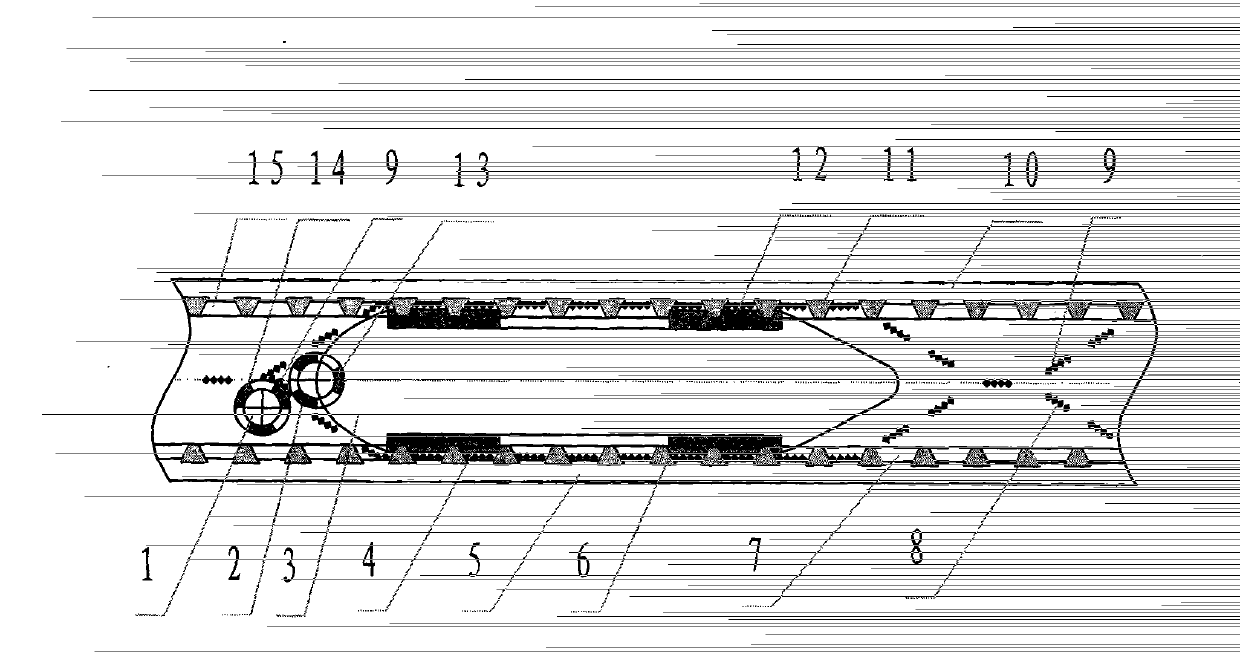
[0011] refer to figure 1 : figure 1 It is a schematic diagram of the structure of an embodiment of a high-speed plastic circular loom that is completely free from warp grinding, 1-shuttle push wheel, 2-shuttle rear wheel, 3-shuttle boat, 4-shuttle boat lower edge magnet, 5-lower door ring, 6-The inner ring magnet of the lower door ring, 7-The warp line passing through the groove of the lower door ring, 8-The warp line A, 9-The warp line B, 10-The upper door ring, 11-The inner ring magnet of the upper door ring, 12-The upper edge magnet of the shuttle boat, 13 - magnets on the outer surface of the shuttle rear wheel, 14 - the magnets on the outer surface of the shuttle wheel, 15 - the upper door ring warp thread passing groove, a kind of warp thread free of rolling high-speed plastic circular loom, it is characterized in that: the rear part of the shuttle boat 3 is installed T...


PUM


Abstract

A high-speed plastic circular weaving machine capable of preventing all strands of warp yarn from being ground comprises an upper door ring, a lower door ring, a shuttle, a shuttle push wheel and a shuttle rear wheel. The peripheral surface of the shuttle rear wheel and the peripheral surface of the shuttle push wheel are provided with magnets with the same polarity, the lower edge of the upper door ring and the upper edge of the lower door ring are respectively provided with magnets which form an inner circle and an outer circle and are arrayed in a V-shaped mode, meanwhile, the lower edge of the upper door ring and the upper edge of the lower door ring are respectively provided with a plurality of warp yarn passing grooves, and the two side edges of the shuttle are respectively provided with one or more magnets. The warp yarn passes through a gap between the magnets of the two wheels and the warp yarn passing grooves of the upper door ring and the lower door ring without being damaged. The high-speed plastic circular weaving machine has the advantages that the warp yarn is prevented from being ground and damaged when plastic woven bags or plastic mesh bags are woven through the circular weaving machine, the failures such as yarn breakage and shuttle flying are effectively avoided, the running speed of the circular weaving machine can be improved by more than 30%, and energy is saved by more than 30%.

Description

technical field [0001] The invention relates to the mechanical field of plastic circular looms, in particular to a high-speed plastic circular loom which is completely free from warp rolling. technical background [0002] At present, the plastic woven bag circular looms and plastic mesh bag circular looms manufactured, sold and used at home and abroad, whether it is the most commonly used four-shuttle circular loom or small six-shuttle circular loom, 8-shuttle circular loom, 12-shuttle circular loom For circular looms, the shuttle wheel and the tail wheel of the shuttle roll to roll and roll the warp thread. The running track of the shuttle boat relies on the roller to roll and roll the warp line on the circular track. Disconnection and shuttle failure often affect normal production. Contents of the invention [0003] The purpose of the present invention is to overcome the above-mentioned defects, and provide a plastic circular loom that does not shuttle, and can run at h...

Claims


Application Information

Patent Timeline
Patent Type & Authority Applications(China)
IPC IPC(8): D03D49/44D03D37/00
Inventor 黄美昌
Owner 黄美昌
Why Eureka
Try Eureka