Cast-in-place shear wall structure equivalent to prefabricated sandwiched superposed shear wall continuous steel bar

A technology of superimposed shear walls and shear walls, which is applied in the direction of walls, building components, and building structures, can solve problems such as unfavorable industrial production applications, inability to apply high-rise buildings, and poor shear resistance, so as to save manpower Effects of resource and construction cost, improvement of structural strength and shear resistance, construction quality and improvement of seismic level

Active Publication Date: 2014-03-12
CHANGSHA BROAD HOMES IND GRP CO LED
View PDF9 Cites 14 Cited by
  • Summary
  • Abstract
  • Description
  • Claims
  • Application Information

AI Technical Summary

Problems solved by technology

[0002] The existing laminated shear wall has no sandwich insulation layer. When the upper and lower walls are installed, the steel bars are not connected to each other. Only vertical steel bars are placed in the middle of the cast-in-place concrete layer between the outer leaf plate and the inner leaf plate of the wall. , this kind of superimposed shear wall connected by a single steel bar on the upper and lower walls has poor shear resistance and low structural strength. Generally, it can only be applied in low-rise buildings, not high-rise buildings. Moreover, the construction is difficult and the labor cost is high. , not conducive to industrial production application

Method used


Image

  • Cast-in-place shear wall structure equivalent to prefabricated sandwiched superposed shear wall continuous steel bar
  • Cast-in-place shear wall structure equivalent to prefabricated sandwiched superposed shear wall continuous steel bar

Examples


Embodiment Construction

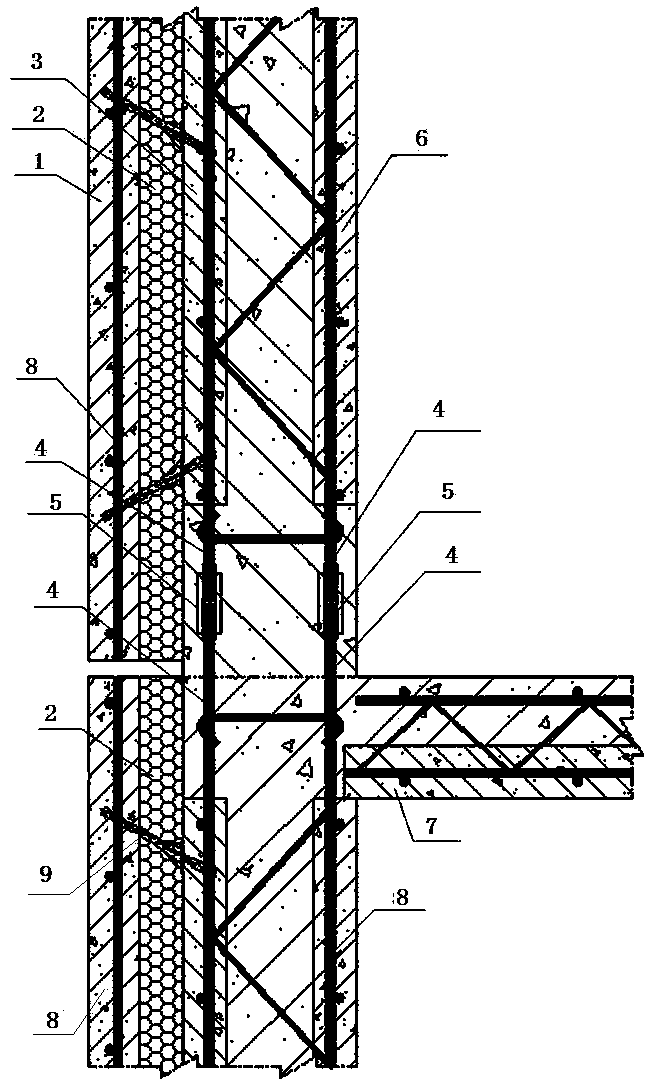
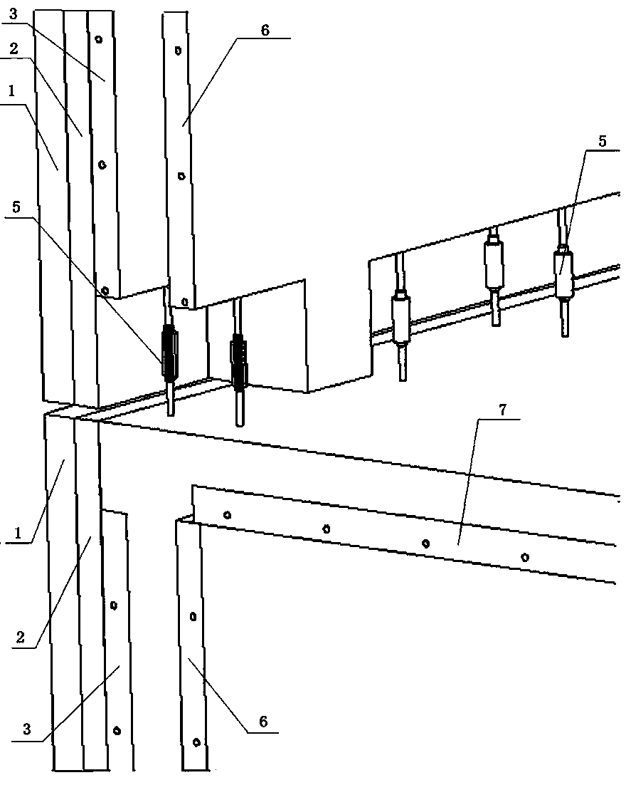
[0012] Referring to the accompanying drawings, the continuous steel bar of the prefabricated sandwich laminated shear wall of the present invention is equivalent to the cast-in-place shear wall structure, and the prefabricated sandwich laminated shear wall is composed of a prefabricated laminated shear wall outer leaf plate, an insulation layer, and a prefabricated laminated shear wall. The middle plate of the wall, the lattice steel bar, and the inner leaf plate of the prefabricated laminated shear wall are connected. The outer leaf plate and insulation layer of the shear wall and the steel bars protrude. When the building is installed, the middle plate and the inner leaf plate of the upper prefabricated laminated shear wall protrude downward and the steel bars are respectively connected with the middle plate and the inner plate of the lower prefabricated laminated shear wall. The blades protrude upwards and are fixedly connected with steel bars, and concrete is poured between...


PUM


Abstract

The invention provides a cast-in-place shear wall structure equivalent to a prefabricated sandwiched superposed shear wall continuous steel bar, the cast-in-place shear wall structure is formed by connecting a prefabricated superposed shear wall outer acanthus, an insulating layer, a prefabricated superposed shear wall intermediate plate, a lattice steel bar and a prefabricated superposed shear wall inner acanthus, the upper ends and the lower ends of the prefabricated superposed shear wall intermediate plate and the prefabricated superposed shear wall inner acanthus are all shorter than the prefabricated superposed shear wall outer acanthus and the insulating layer, and the steel bar extends out; in construction and installation, the downward extended steel bars of the upper layer prefabricated superposed shear wall intermediate plate and inner acanthus are respectively fixedly connected with the upward extended steel bars of the lower layer prefabricated superposed shear wall intermediate plate and inner acanthus, and concrete is cast between the intermediate plate and the inner acanthus to form a structure system containing the insulating layer and equivalent to the cast-in-place shear wall. The cast-in-place shear wall structure provided by the invention is insulating and energy-saving, strong in seismic capacity, structure strength and anti-shear capacity, the technical problem that the sandwiched superposed shear wall cannot be applied to the high-rise building is broke through, and the industrial production is realized.

Description

technical field [0001] The invention relates to the technical field of construction engineering, in particular to a prefabricated sandwich laminated shear wall continuous reinforcement equivalent to a cast-in-place shear wall structure. Background technique [0002] The existing laminated shear wall has no sandwich insulation layer. When the upper and lower walls are installed, the steel bars are not connected to each other. Only vertical steel bars are placed in the middle of the cast-in-place concrete layer between the outer leaf plate and the inner leaf plate of the wall. , this kind of superimposed shear wall connected by a single steel bar on the upper and lower walls has poor shear resistance and low structural strength. Generally, it can only be applied in low-rise buildings, not high-rise buildings. Moreover, the construction is difficult and the labor cost is high. , which is not conducive to industrial production and application. Contents of the invention [000...

Claims


Application Information

Patent Timeline
Patent Type & Authority Applications(China)
IPC IPC(8): E04B2/56
Inventor 张剑
Owner CHANGSHA BROAD HOMES IND GRP CO LED
Why Eureka
Try Eureka