
Metal floor and formation method

A metal floor and floor technology, which is applied in construction, construction material processing, building construction, etc., can solve the problem of easy to emit loud noise, and achieve the effect of eliminating noise.

Active Publication Date: 2014-03-12
中国冶金科工股份有限公司
View PDF8 Cites 7 Cited by
  • Summary
  • Abstract
  • Description
  • Claims
  • Application Information

AI Technical Summary

Problems solved by technology

[0004] The invention provides a metal floor and its forming method, aiming to solve the problem that the current metal floor tends to make loud noises when in use

Method used


Image

  • Metal floor and formation method

Examples


Embodiment 1

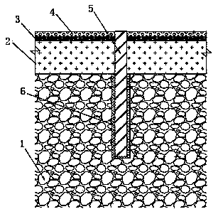
[0028] Such as figure 1 As shown, a metal floor described in this embodiment includes a reinforced concrete layer 1, a fine stone concrete layer 2, a rubber layer 3, a steel plate layer 4, and several threaded steel columns 5 from bottom to top. 5 runs through the steel plate layer 4, rubber layer 3, and fine stone concrete layer 2 in sequence, and is inserted into the reinforced concrete layer 1. The upper end of the threaded steel column 5 is flush with the upper surface of the steel plate layer 4, and the fine stone concrete layer 2, rubber layer 3 1. The steel plate layer 4 is stably connected with the reinforced concrete layer 1 under the action of the threaded steel column 5 as a whole.

[0029] In order to ensure that the bottom layer has a higher strength, the reinforced concrete layer 1 of this embodiment is C55 concrete, and in order to realize leveling more conveniently and quickly, the fine stone concrete layer 2 adopts C25 fine stone concrete.

[0030] As prefer...

Embodiment 2

[0033] This embodiment is basically the same as Embodiment 1, the difference is that high-strength building rebar glue 6 is filled between the threaded steel column 5 and the reinforced concrete layer 1 in this embodiment, which is used to improve the pull-out resistance of the threaded steel column 5 force.

[0034] A forming method for realizing the above-mentioned metal floor, comprising the following process steps:

[0035] Step (1), after the reinforced concrete layer is formed and solidified, remove the debris and floating soil on the upper surface of the reinforced concrete layer, pour fine stone concrete, level it, and the height of the leveling layer is 4~5cm, that is, the thickness of the fine stone concrete is kept at 4~ 5cm, the upper surface of the fine stone concrete is as flat as possible and located on the same level;

[0036] Step (2), after pouring the fine stone concrete, water and cure for 6-8 days, so that the solidification strength of the fine stone con...


PUM

PropertyMeasurementUnit
diameteraaaaaaaaaa
thicknessaaaaaaaaaa
thicknessaaaaaaaaaa

Abstract

The invention discloses a metal floor and a formation method. The metal floor sequentially comprises a steel bar concrete layer (1), a fine stone concrete layer (2), a rubber layer (3) and a steel plate layer (4) from bottom to top, and further comprises a plurality of threaded steel pillars (5). The threaded steel pillars (5) sequentially penetrate through the steel plate layer (4), the rubber layer (3) and the fine stone concrete layer (2), and are inserted into the steel bar concrete layer (1), the upper ends of the threaded steel pillars (5) are flush with the upper surface of the steel plate layer (4), the steel bar concrete layer (1) is made of C55 concrete, and the fine stone concrete layer (2) is made of C25 fine stone concrete. Due to the adoption of the structure, the structure of the metal floor has certain rigidity and strength, noise is reduced or even eliminated, and therefore the whole metal floor can completely meet the requirements.

Description

technical field [0001] The invention relates to the field of building construction, in particular to a metal floor and a forming method. Background technique [0002] Floor is a general term for all kinds of ground, which refers to the use of certain tools and materials combined with corresponding construction techniques to finally make the ground show a certain decorative effect or special function, such as epoxy self-leveling floor, emery wear-resistant floor, Super flat floor, epoxy terrazzo floor, epoxy colored sand floor, epoxy non-slip floor, polyurethane floor, etc. The floor is the part of the ground-floor room in contact with the soil layer. It bears the load of the ground-floor room and requires a certain strength and rigidity. [0003] At present, in order to increase the strength of the floor and play an anti-theft role in the bank's cash operation center treasury or some important warehouses and secret rooms, metal floors are usually used, and the current commo...

Claims


Application Information

Patent Timeline
Patent Type & Authority Applications(China)
IPC IPC(8): E04F15/00E04F15/12C04B28/00E04G21/00
Inventor 范兴华雷云辉李建虎
Owner 中国冶金科工股份有限公司
Learn More