Mining method of layering and non-segmented roadway filling in downward approach of broken surrounding rock ore body

A technology of crushing surrounding rock and filling mining, which is applied in underground mining, filling, ground mining, etc., can solve the problem of less research on roadway support technology for metal ore crushing surrounding rock, which is unfavorable for the sustainable development of mine economy and consumes a lot of manpower , material resources and other issues, to achieve the effect of reducing the cost of mining equipment, simplifying the layout of mining tunnels, and reducing mining costs

Inactive Publication Date: 2015-08-12
SHANDONG UNIV OF SCI & TECH
View PDF5 Cites 10 Cited by
  • Summary
  • Abstract
  • Description
  • Claims
  • Application Information

AI Technical Summary

Problems solved by technology

[0004] First of all, the mining system of the downward approach layered filling mining method is particularly complicated, and a considerable number of tunnels need to be excavated to meet the production demand. For the inclined thin ore body with a thickness of less than 5m, due to its small reserves, if Adopting the original arrangement will inevitably lead to a further increase in the 1,000-ton cutting ratio, thereby increasing production costs and consuming a lot of manpower and material resources, which is not conducive to the sustainable development of the mine economy.
[0005] Secondly, the downward approach layered filling mining method of the existing technology only relies on the overlying filling body to reduce the loss rate and dilution rate by reducing the exposed space, while the roadway support technology for the broken surrounding rock ore body of metal ore relatively few studies

Method used


Image

  • Mining method of layering and non-segmented roadway filling in downward approach of broken surrounding rock ore body
  • Mining method of layering and non-segmented roadway filling in downward approach of broken surrounding rock ore body
  • Mining method of layering and non-segmented roadway filling in downward approach of broken surrounding rock ore body

Examples


Embodiment Construction

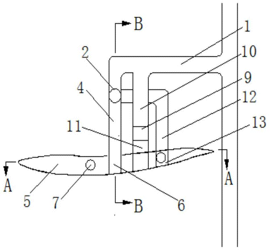
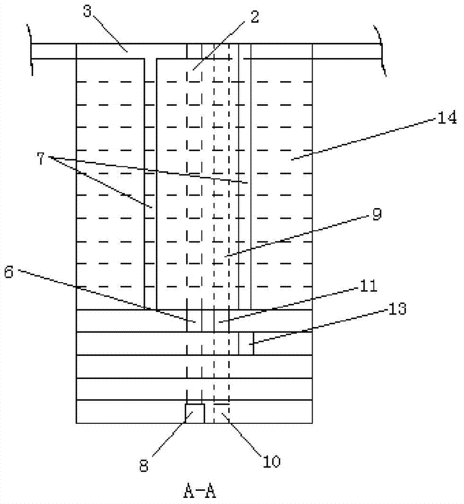
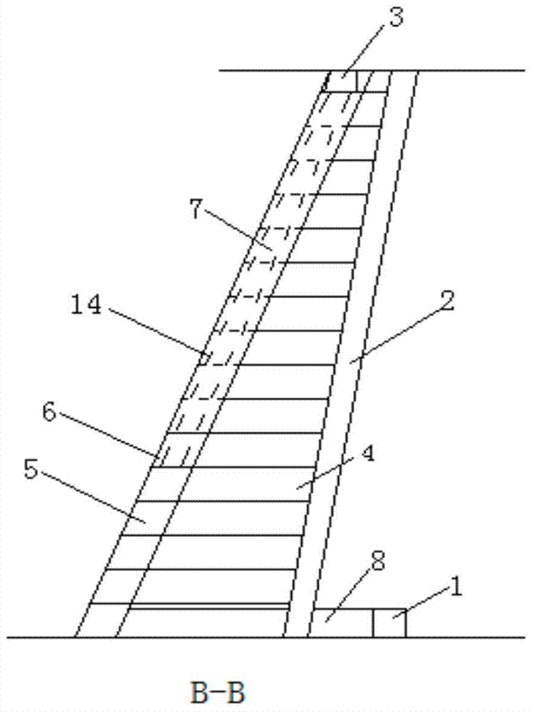
[0030] The stope layout of the mine method for layering and non-segmented roadway filling in the downward approach of the broken surrounding rock ore body of the present invention will be described in detail below in conjunction with the accompanying drawings.

[0031] Such as Figure 1 to Figure 3 As shown, the broken surrounding rock ore body of the present invention has a downward approach layered non-section roadway filling mining method, and its corresponding broken surrounding rock ore body stope arrangement is as follows: stope main transport lane 1, slip shaft 2, along the vein Air return lane 3, chute connection road 4, ore body 5, layered level roadway 6, filling-return air shaft 7, vein-piercing transport road 8, pedestrian ventilation patio 9, vein-piercing air inlet duct 10, cutting level lane 11, The lower layer chute connecting road 12, the lower layer drift 13, and the overlying filling body 14.

[0032] Below, taking a gold mine as an example, the mining meth...


PUM


Abstract

The invention discloses a crushed surrounding rock ore downward drift layered sublevel-free tunnel filling mining method, the method comprises the following steps: adopting a mode of not setting a layered linking way, a sublevel tunnel and a pulse external ramp aiming at the special condition that the thickness of the inclined thin ore is less than 5m, adopting single tunnel drift type stoping when an accurate mining tunnel is arranged, determining the drift as a parallelogram; protecting an hanging wall surrounding rock and a footwall surrounding rock by adopting an anchor net cable joint support way; adopting underholing-free millisecond blasting technology for ore break down; computing the thickness of a filler bearing layer according to a built-in beam principle, differentially filling a gob, and adding a certain amount of complex early strength agent into the bearing layer material to fast setting and stabilizing the bearing layer. The tunnel arrangement is simplified, the construction difficulty is reduced, the drift tunnel excavating cost is lowered, the ore dilution rate and loss rate are reduced, and the safe and efficient production in the inclined thin ore exploitation process is realized.

Description

technical field [0001] The invention relates to a layered filling mining method with a downward approach, in particular to a layered and non-segmented roadway filling mining method with a broken surrounding rock ore body and a downward approach. Background technique [0002] The downward approach layered filling mining method is a new concept mining method developed in the 1950s. This method is suitable for mining extremely unstable ore bodies with high value. When the thickness of the ore body is less than 20m, the approach is arranged along the strike; when the thickness of the ore body is greater than 20m, the approach is arranged vertically. Initially, this method was used for two-step pillar recovery, and now it is widely used in difficult-to-mining ore bodies with rock crushing and complex mining technical conditions. [0003] However, there are some deficiencies and problems in the downward approach layered filling mining method of the prior art, mainly in the follow...

Claims


Application Information

Patent Timeline
Patent Type & Authority Patents(China)
IPC IPC(8): E21C41/22E21F15/00
Inventor 郭忠平冯帆樊明玉王兴涛张阳阳
Owner SHANDONG UNIV OF SCI & TECH
Why Eureka
Try Eureka