Pump device

A technology of pump device and drive device, applied in pump control, liquid variable capacity machinery, machine/engine, etc., to achieve the effect of high flexibility

Inactive Publication Date: 2014-03-12
ROBERT BOSCH GMBH
View PDF6 Cites 0 Cited by
  • Summary
  • Abstract
  • Description
  • Claims
  • Application Information

AI Technical Summary

Problems solved by technology

[0003] The disadvantage of this pump arrangement is that it serves to supply the load with two pressure spaces arranged opposite to each other

Method used


Image

  • Pump device
  • Pump device

Examples


Embodiment Construction

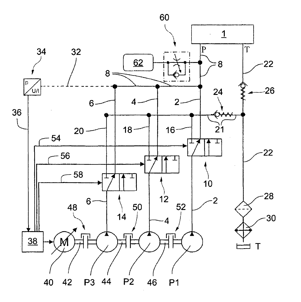
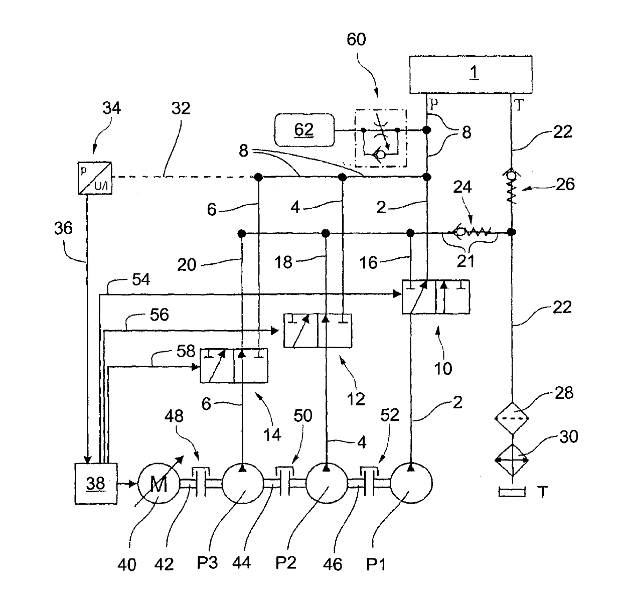
[0033] figure 1 An exemplary embodiment of the pump device according to the invention is shown in the case of a maximum volumetric flow requirement of a load 1 connected to the pump device, which is designed as a constant pressure system. The pump arrangement has three metering pumps P1 , P2 , P3 connected in parallel. They are arranged in an open loop and have working lines 2, 4, 6 respectively. The working lines 2 , 4 , 6 feed into a common high-pressure line 8 , via which the load 1 is supplied with pump pressure.

[0034] The three metering pumps can have different nominal delivery volumes, according to which a distinction is made below between the large metering pump P3 , the middle metering pump P2 and the small metering pump P1 . The small fixed displacement pump P1 is designed for zero-stroke operation or pressure-maintained drive.

[0035] Distribution valves 10 , 12 , 14 are provided in the working lines 2 , 4 , 6 respectively. Each distribution valve 10, 12, 14 ...


PUM


Abstract

The invention discloses a pump device. Preferably, the pump device is a constant pressure system and comprises a plurality of fixed displacement pumps in parallel, and the fixed displacement pumps are all driven by a rotating speed changeable driving device. Each fixed displacement pump is provided with an auxiliary working pipeline, a distribution valve is arranged in each auxiliary working pipeline, and conveying volume flow of the auxiliary fixed displacement pumps can be led out from grooves through the distribution valves. The working pipelines are combined in a public high-pressure pipeline of the pump device. According to the pump device, the distribution valves, used for removing activation or invaliding connection or used for carrying out activating or connecting, of the belonging fixed displacement pumps can be switched on or switched off or operated by depending on respective threshold rotating speed of the speed changeable driving device. Preferably, the operation is achieved through a regulating loop. Therefore, the pump device can be driven in a rotating speed changeable mode in a wide rotating speed band to a large extent.

Description

technical field [0001] The invention relates to a pump device and a method for operating it. Background technique [0002] EP 1 564 414 A1 publication discloses a pump arrangement according to the subject matter of the invention as claimed in claim 1 , in which a hydraulic load is supplied or driven by two fixed displacement pumps coupled to one another and by a common speed-variable drive. As long as a predetermined load pressure is not exceeded, the two pumps are deactivated or inactively connected via the distribution valve by connecting their high-pressure connections to the tank. The switching of the distribution valve takes place via a control line in which the load pressure of the hydraulic load is present, ie the distribution valve is a pressure distribution valve. [0003] A disadvantage of this pump arrangement is that it serves to supply two pressure spaces arranged opposite one another. Contents of the invention [0004] In contrast, the object of the present...

Claims


Application Information

Patent Timeline
Patent Type & Authority Applications(China)
IPC IPC(8): F04B49/00
Inventor T·格尔纳
Owner ROBERT BOSCH GMBH
Why Eureka
Try Eureka