
Self-adjusting clutch with induction spring

A clutch and self-adjusting technology, applied in the field of clutches, can solve the problems of reducing the service life of the clutch, increasing the working pressing force, and increasing the maximum separation force of the separation clutch, so as to ensure normal use, prolong the service life, and have a reliable and durable structure. Effect

Active Publication Date: 2014-03-12
NINGBO HONGXIE CLUTCH
View PDF7 Cites 5 Cited by
  • Summary
  • Abstract
  • Description
  • Claims
  • Application Information

AI Technical Summary

Problems solved by technology

[0003] During the long-term application of the clutch, due to the driver's repeated use, it is easy to cause wear on the friction plate connected to the clutch. Due to the wear of the friction plate, the pressure plate will shift, which will cause the large end of the diaphragm spring to deform. If the pressure is reduced, the working pressing force will increase, and the maximum separation force required for the separation clutch will also increase at this time, which will increase the force required for the driver to step on the clutch, which will affect the driving comfort and reduce the service life of the clutch.

Method used


Image

  • Self-adjusting clutch with induction spring
  • Self-adjusting clutch with induction spring
  • Self-adjusting clutch with induction spring

Examples


Embodiment Construction

[0025] Below in conjunction with specific embodiment, further illustrate the present invention. It should be understood that these examples are only used to illustrate the present invention and are not intended to limit the scope of the present invention. In addition, it should be understood that after reading the teachings of the present invention, those skilled in the art can make various changes or modifications to the present invention, and these equivalent forms also fall within the scope defined by the appended claims of the present application.

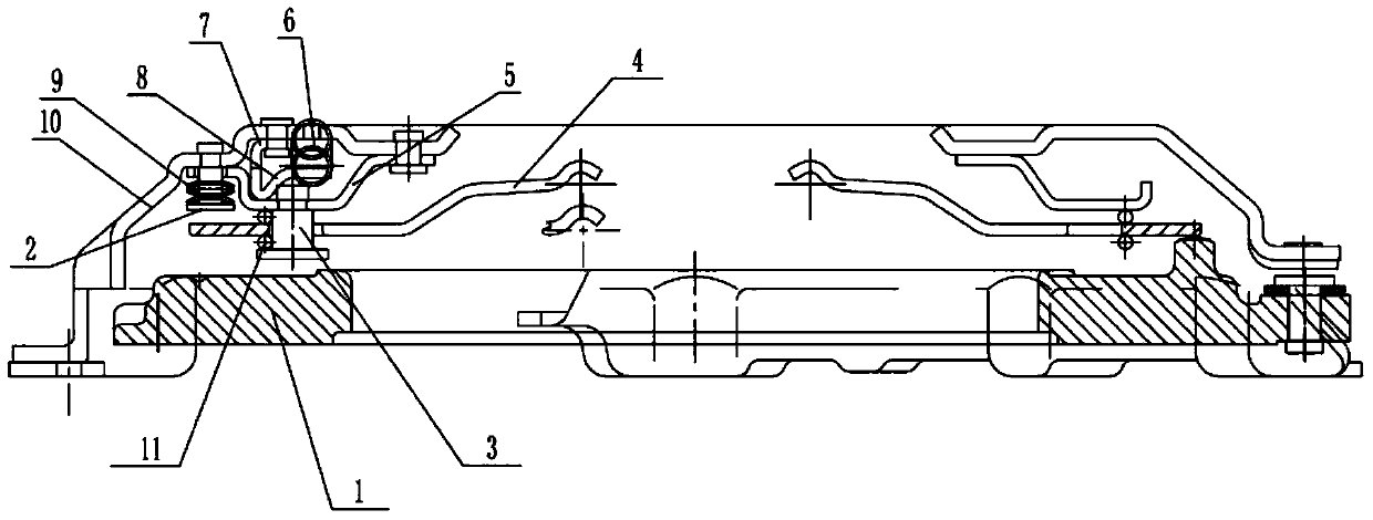
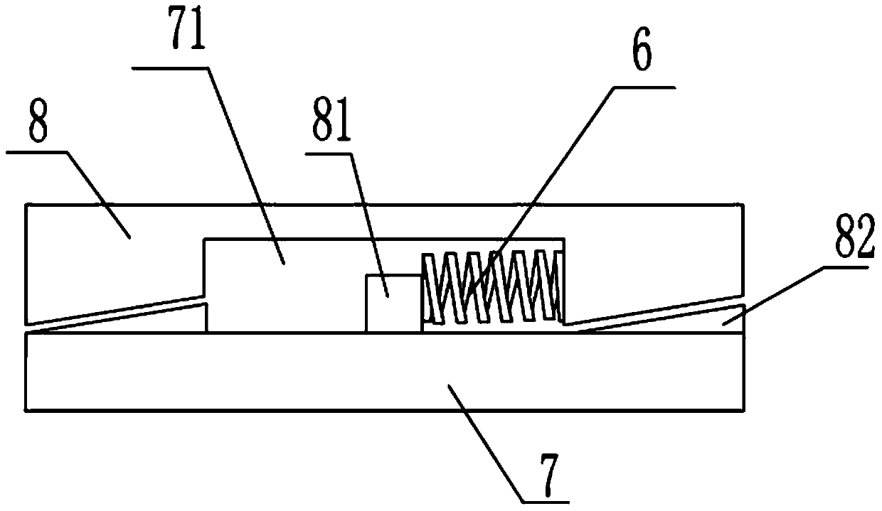
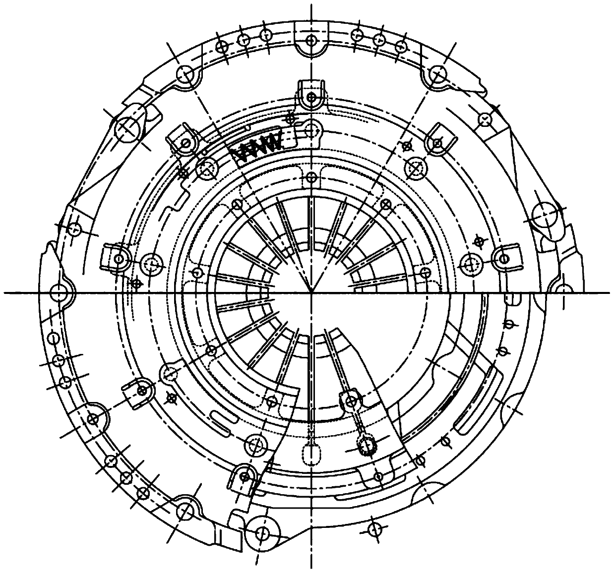
[0026] Such as Figure 1-7 As shown, the embodiment of the present invention relates to a self-adjusting clutch equipped with an induction spring, including a pressure plate 1, a clutch upper cover 10 and a diaphragm spring 4, and the pressure plate 1 is fixedly installed on the lower end of the clutch upper cover 10 Inside, the inside of the clutch upper cover 10 is arranged with a ring of diaphragm springs 4 around the cente...


PUM


Abstract

The invention relates to a self-adjusting clutch with an induction spring. The self-adjusting clutch comprises a pressing plate, a clutch upper cover and a diaphragm spring. The pressing plate is fixedly installed on the inner side of the lower end of the clutch upper cover. A circle of diaphragm spring is arranged inside the clutch upper cover around the circle center. The lower end of the top face of the clutch upper cover provided with an annular connecting plate in a connected mode, the position, close to the outer side end, of the diaphragm spring is connected with the annular connecting plate through a plurality of lower rivets which are evenly arranged, a self-adjusting device is installed between the annular connecting plate and the clutch upper cover, an elastic piece is arranged inside the self-adjusting device, the lower end of the self-adjusting device abuts against the annular connecting plate all the time, the outer side end of the annular connecting plate is connected with the clutch upper cover through long rivets which are evenly distributed, and the long rivets are sleeved with induction springs. The self-adjusting clutch is simple in structure, a gap caused by the abrasion of a friction plate can be automatically compensated through the clutch due to the cooperated usage of the induction springs and the self-adjusting device, and the normal usage of the clutch is guaranteed.

Description

technical field [0001] The invention relates to the clutch field, in particular to a self-adjusting clutch equipped with an induction spring. Background technique [0002] The clutch is installed between the engine and the transmission, and is an assembly directly connected with the engine in the car drive train. Usually, the clutch is installed together with the flywheel set of the engine crankshaft, which is the part that cuts off and transmits power between the engine and the vehicle transmission system. During the whole process of the car from starting to normal driving, the driver can manipulate the clutch as needed to temporarily separate or gradually engage the engine and drive train to cut off or transfer the power output from the engine to the drive train. Its function is to make the engine and the transmission gradually engage, so as to ensure the smooth start of the car; temporarily cut off the connection between the engine and the transmission, so as to facilita...

Claims


Application Information

Patent Timeline
IPC IPC(8): F16D13/75
Inventor 胡宏谢剑云王善南张琼叶
Owner NINGBO HONGXIE CLUTCH
Learn More