
Friction component used for wet-type friction clutch

A friction clutch and friction locking technology, applied in the field of friction components, can solve problems such as failure to be fully and effectively implemented

Inactive Publication Date: 2014-03-12
SCHAEFFLER TECH AG & CO KG
View PDF8 Cites 5 Cited by
  • Summary
  • Abstract
  • Description
  • Claims
  • Application Information

AI Technical Summary

Problems solved by technology

In the currently known wet friction clutches, the solution of heat removal through oil has not been implemented sufficiently effectively

Method used


Image

  • Friction component used for wet-type friction clutch
  • Friction component used for wet-type friction clutch
  • Friction component used for wet-type friction clutch

Examples


Embodiment Construction

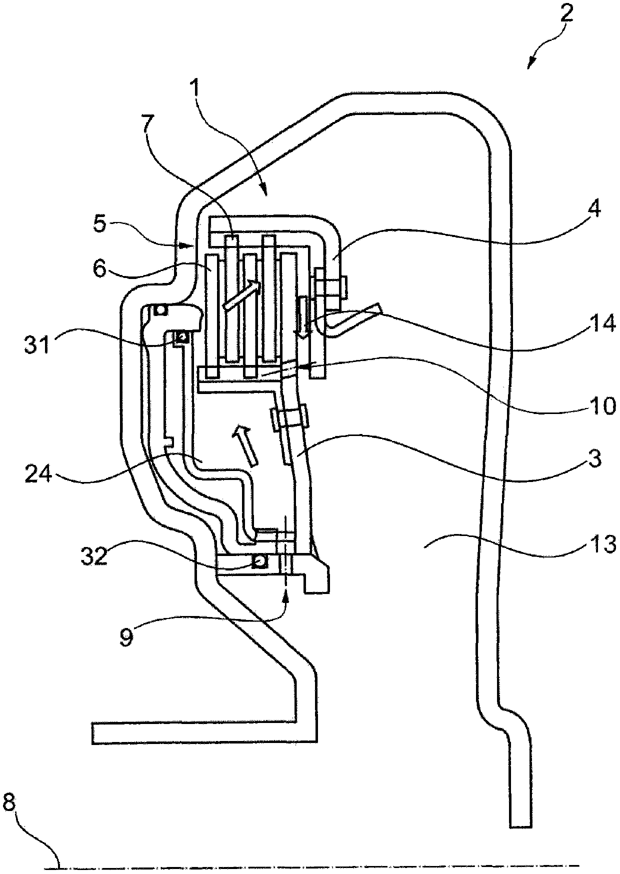
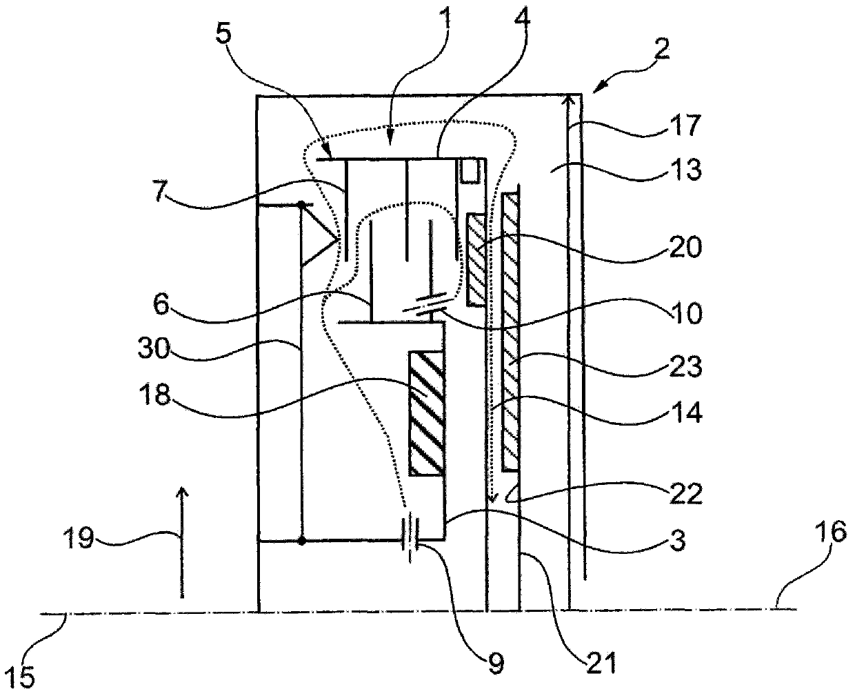
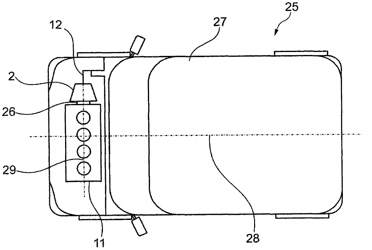
[0044] figure 1 is a sectional view of a wet friction clutch 2 comprising a friction pack 1 consisting of an inner disc carrier 3 and an outer disc carrier 4 . The inner disk carrier 3 and the outer disk carrier 4 each have a plurality of first disks 6 and second disks 7 . The first friction plate 6 and the second friction plate 7 are located in the friction plate chamber 5 . Formed in the first lining carrier 3 is a first through-opening 9 through which coolant can enter, pass through the first lining carrier 6 and the second lining 7 and return along the outer lining carrier 4 and again through the second lining carrier Two through openings 10 enter the friction lining chamber 5 . A feed line 24 to the friction lining chamber 5 , which is statically sealed by a first static seal 31 and a second seal 32 , is connected to the first through-opening 9 . In the partial schematic view of the wet friction clutch 2 , only the central shaft 8 is schematically shown, around which t...


PUM


Abstract

The invention relates to a friction component used for a wet-type friction clutch comprising an internal friction sheet carrier; an external friction sheet carrier; a friction sheet chamber used for accommodating the friction sheets to transmit the torque in a locked manner; a central shaft, around which rotates the friction sheet carrier. The internal friction sheet carrier is provided with a first through opening and a second through opening. The first through opening is extended from the central shaft to the friction sheet chamber, and the second through opening is extended from the outer side of friction sheet chamber to the friction sheet chamber. By using the wet-type friction clutch or the friction component can be used to utilize the cooling efficiency of the cooling liquid, reduce the required structural space and the production costs.

Description

technical field [0001] The present invention relates to a friction assembly for a wet friction clutch, and a wet friction clutch having such a friction assembly. In particular, the friction assembly or the wet friction clutch can be used in a motor vehicle with an internal combustion engine or an electric motor. In this case, the friction pack or wet friction clutch is suitable for detachably connecting a rotating input shaft with a stationary or slowly rotating output shaft. Background technique [0002] Frictional heat is generated when connecting two shafts with different rotational speeds. In order to be able to dissipate this heat adequately, the friction pack or wet friction clutch must be designed with sufficient thermal mass. If the friction clutch is designed dry, ie without coolant, the thermal mass is formed by structural parts of the friction clutch or of the friction pack. However, such dry friction clutches are not suitable for many applications because they...

Claims


Application Information

Patent Timeline
Patent Type & Authority Applications(China)
IPC IPC(8): F16D25/0638F16D13/68F16D13/72B60K5/04B60K17/02
CPCF16D2300/0214F16D25/123F16D25/0638F16D13/72
Inventor T·居吕克M·屈恩勒
Owner SCHAEFFLER TECH AG & CO KG
Learn More