Variable inertia reaction flywheel

A technology of reactive flywheel and variable inertia, which is applied in auxiliary non-electrical speed/acceleration control, etc., can solve the problems of high energy consumption, difficult power supply of motors, and difficulty in detecting system mass distribution, and achieves the effect of simple structure and enlarged scope.

Inactive Publication Date: 2014-03-12
BEIJING UNIV OF TECH
View PDF6 Cites 5 Cited by
  • Summary
  • Abstract
  • Description
  • Claims
  • Application Information

AI Technical Summary

Problems solved by technology

The existing variable inertia reaction flywheel has the problems of difficulty in adjusting the mass distribution of the s

Method used


Image

  • Variable inertia reaction flywheel
  • Variable inertia reaction flywheel
  • Variable inertia reaction flywheel

Examples


Embodiment Construction

[0013] The present invention will be further described below in conjunction with the accompanying drawings.

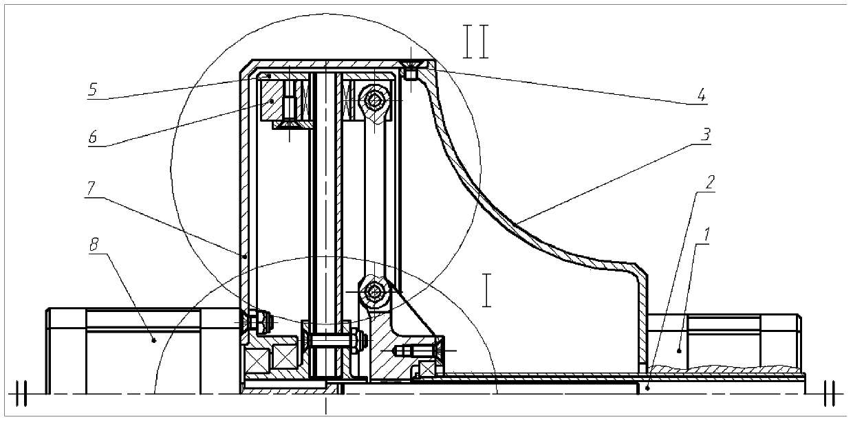
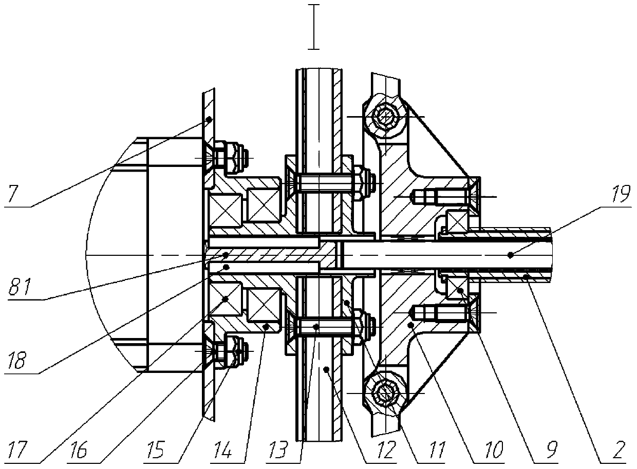
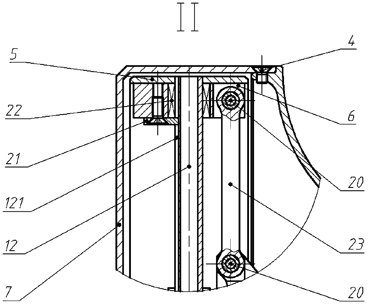
[0014] Such as figure 1 Shown is the structure diagram of the variable inertia reaction flywheel, figure 2 Partial enlarged view I for the variable inertia reaction flywheel, image 3 In order to change the inertia, use the flywheel to partially enlarge the view II. The variable inertia reaction flywheel includes the lead screw motor 1, the lead screw 2, the right housing 3, the screw a4, the wheel outer ring 5, the counterweight 6, the left housing 7, the drive Motor 8, deep groove ball bearing a9, slider 10, flywheel shaft 11, guide rod 12, screw b13, support 14, self-locking nut 15, screw c16, deep groove ball bearing b17, flat key 18, guide rod 19, Pin shaft 20, anti-twist block 21, sliding bearing 22 and connecting rod 23, wherein drive motor 8 is provided with drive motor shaft 81, and guide bar 12 is provided with anti-twist groove 121; The ring 5 is connect...


PUM


Abstract

The invention relates to a variable inertia reaction flywheel. A flywheel shaft is linked with a flywheel outer ring by virtue of a guide bar; the flywheel shaft is arranged on a support by virtue of a deep groove ball bearing; the support is fixed on a left shell; a drive motor is fixed on the left shell, and the shaft of the drive motor is linked with the flywheel shaft by virtue of a flat key, so as to drive the flywheel to rotate; the guide bar is provided with a balancing weight which can slide along the guide bar; the flywheel shaft is provided with a guide rod of which the axis is superposed with the axis of the flywheel; the guide rod is provided with a slide block; the slide block is linked with the balancing weight by virtue of a connecting rod; the other end of the slide block is linked with a lead screw by virtue of a deep groove ball bearing; a right shell and a left shell are oppositely fixed; a through screw rod motor is arranged on the right shell; the lead screw motor drives the lead screw to do spiral movement; the lead screw drives the slide block to slide along the guide rod, so as to drive the balancing weight to slide along the guide bar, and thus the rotary inertia of a flywheel mechanism is adjusted; the counter torque output by the variable inertia reaction flywheel is controlled by controlling the angular speed of the drive motor and the angle of revolution of the lead screw motor.

Description

technical field [0001] The invention relates to a reaction flywheel, which belongs to the field of reaction flywheels used for attitude adjustment, in particular to a reaction flywheel with variable inertia. Background technique [0002] As a key component of attitude adjustment, the reaction flywheel has been widely used in the fields of satellites, one-wheeled robots and other aircraft and robots. A reaction flywheel is installed inside the object, and the attitude of the object can be controlled by driving the reaction flywheel to obtain the reaction torque. When the object performs rapid and large-angle attitude maneuvers, it generally requires a large reaction torque; while it requires a small amount of high-precision attitude adjustment. The reaction torque adjusts the attitude. Due to the limitation of the speed of the reaction flywheel and the control accuracy of the motor, a large reaction torque is generally provided, and a reaction flywheel with a large moment of...

Claims


Application Information

Patent Timeline
IPC IPC(8): G05D13/58
Inventor 阮晓钢陈志刚张晓平魏若岩肖尧庞涛
Owner BEIJING UNIV OF TECH
Why Eureka
Try Eureka