Gyrotron collector

A collector and gyrotron technology, applied in the microwave field, can solve problems such as messy electrons, instability of high-power gyrotrons, failure of all gyrotron beams to land, etc., and achieve the effect of improving stability and increasing power capacity

Inactive Publication Date: 2014-03-12
INST OF ELECTRONICS CHINESE ACAD OF SCI
View PDF5 Cites 2 Cited by
  • Summary
  • Abstract
  • Description
  • Claims
  • Application Information

AI Technical Summary

Problems solved by technology

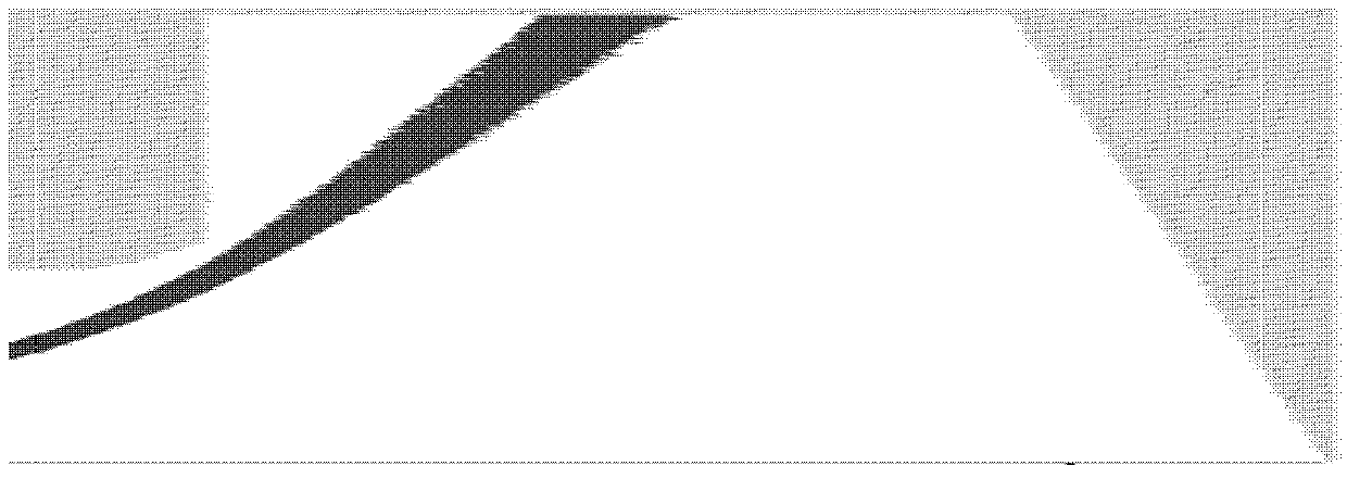
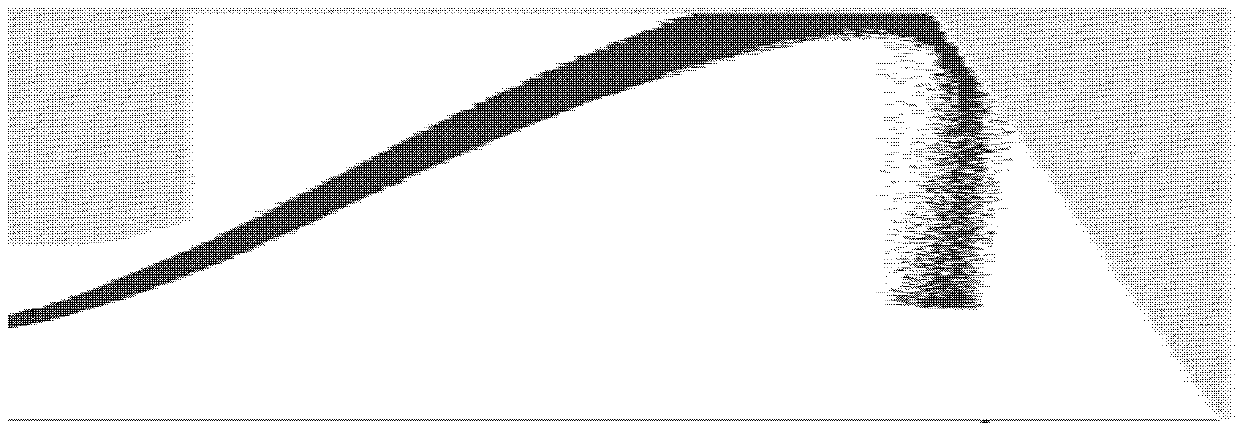
Compared figure 1 It can be seen from Fig. 2 that although the landing width of the cyclotron beam on the collector wall has increased, due to the influence of the charge force between the electron beams and the interference of the electromagnetic field, the cyclotron beam cannot completely land on the collector wall.
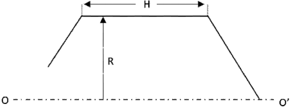
[0006] In the process of realizing the present invention, the applicant found that the conventional conical structure of the gyrotron collector has the following defects

Method used


Image

  • Gyrotron collector
  • Gyrotron collector
  • Gyrotron collector

Examples


Embodiment Construction

[0023] In order to make the object, technical solution and advantages of the present invention clearer, the present invention will be described in further detail below in conjunction with specific embodiments and with reference to the accompanying drawings.

[0024] It should be noted that, in the drawings or descriptions of the specification, similar or identical parts all use the same figure numbers. Implementations not shown or described in the accompanying drawings are forms known to those of ordinary skill in the art. Additionally, while illustrations of parameters including particular values ​​may be provided herein, it should be understood that the parameters need not be exactly equal to the corresponding values, but rather may approximate the corresponding values ​​within acceptable error margins or design constraints. In addition, the directional terms mentioned in the following embodiments, such as "upper", "lower", "front", "rear", "left", "right", etc., are only re...


PUM


Abstract

The invention provides a gyrotron collector. The gyrotron collector comprises a transition section, a cylinder section which is connected with the transition section in a sealing manner, and a top cover which is connected on the rear side of the cylinder section in a sealing manner. An inner side of the top cover is provided with a bulge toward the cylinder section. The gyrotron collector can effectively intercept and capture abnormal clutter electrons generated by influence of space charge forces among electron beams and disturbance of a high-frequency electromagnetic field excited by the electron beams, and controls the mussy abnormal electrons in an effective region, preventing appearance of uncontrollable air leaking points, and improving work stability of high power gyrotrons.

Description

technical field [0001] The invention belongs to the field of microwave technology, in particular to a gyrotron collector. Background technique [0002] Gyrotron is a new type of coherent microwave radiation source device, which can work in high frequency band and has high power capacity and working bandwidth. Gyrotron is used in imaging radar, electronic countermeasures, directed energy weapons, material processing, plasma heating and other fields It has broad application prospects. [0003] The gyrotron can be divided into two types according to the microwave output structure: one is the gyrotron with an axial output structure, and the gyrotron with this type of structure usually adopts a low-order circular symmetry working mode, and the collector for recycling the cyclotron beam is also a The output channel of high-power microwave is limited by the output waveguide mode conversion, the power capacity of the collector of this type of gyrotron is greatly limited; the other ...

Claims


Application Information

Patent Timeline
IPC IPC(8): H01J23/027
Inventor 耿志辉刘濮鲲粟亦农张世昌顾伟
Owner INST OF ELECTRONICS CHINESE ACAD OF SCI
Why Eureka
Try Eureka