Gas-liquid separator with liquid-storing and liquid-discharging functions

A technology of gas-liquid separator and cyclone separator, which is applied in separation methods, dispersed particle separation, chemical instruments and methods, etc., can solve the problems of low separation efficiency, large volume, and no drainage function, etc., to improve separation efficiency. , the effect of reducing the size

Active Publication Date: 2014-03-19
SHANGHAI JIAO TONG UNIV
View PDF5 Cites 8 Cited by
  • Summary
  • Abstract
  • Description
  • Claims
  • Application Information

AI Technical Summary

Problems solved by technology

[0002] The existing gas-liquid separator has a large pressure drop and a large volume. The separation of gas and liquid in the gas-liquid two-phase flow is achieved solely by gravity or centrifugal force. The separation efficiency is low, and it is not suitable for the gas-liquid mixture with low dryness. Separation, and most separators can only realize the separation of gas and liquid, without the function of liquid discharge

Method used


Image

  • Gas-liquid separator with liquid-storing and liquid-discharging functions
  • Gas-liquid separator with liquid-storing and liquid-discharging functions
  • Gas-liquid separator with liquid-storing and liquid-discharging functions

Examples


Embodiment 1

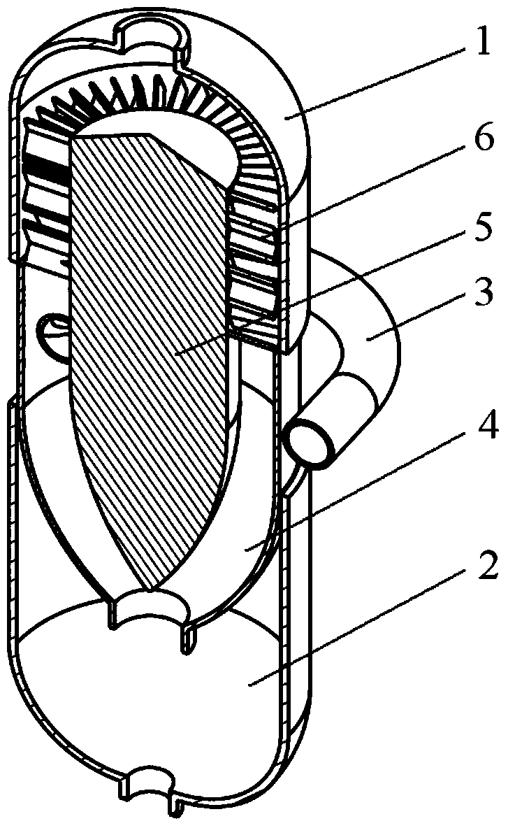
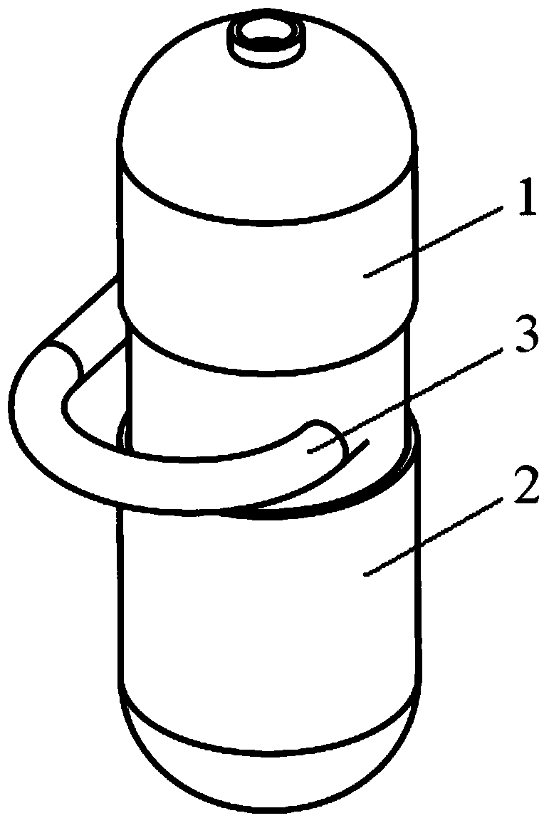
[0025] A gas-liquid separator with liquid storage and liquid discharge functions, its structure is as follows Figure 1-2 As shown, it includes the upper cylinder 1 and the lower cylinder 2 nested, the arc-shaped liquid pipe 3 arranged outside the cylinder, the cyclone separator 4 arranged in the cylinder, the flow-around core 5 and the deflection points. Liquid plate6. The flow-around core 5 is arranged inside the cyclone separator 4 , an annular space is formed between the cyclone separator 4 and the flow-around core 5 , and the baffle and separator plate 6 is sleeved on the outside of the flow-around core 5 .

[0026] A gas outlet is provided at the top of the upper cylinder 1, and a liquid outlet is provided at the bottom of the lower cylinder 2. The upper part of the cyclone separator 4 is a cylindrical cylinder, the lower part is an arc-shaped cylinder with a reduced cross-section, and the bottom has an opening. The arc-shaped liquid distribution pipe 3 is connected to ...

Embodiment 2

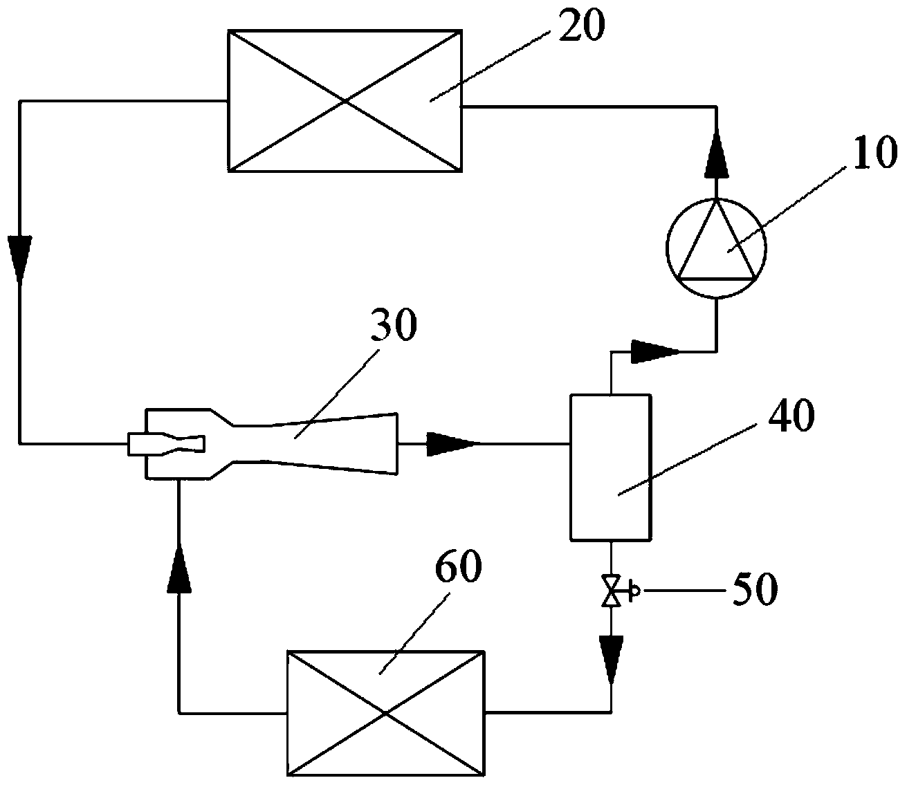
[0029] Ejector system with gas-liquid separator

[0030] The structure of the present invention applied in the injector system is as image 3 As shown, this embodiment is a refrigeration system with an ejector, which is composed of a compressor 10 , a condenser 20 , a gas-liquid separator 40 , an ejector 30 , a throttle valve 50 and an evaporator 60 . The connection relationship between the components: the outlet of the compressor 10 is connected to the inlet of the condenser 20, and then the outlet of the condenser 20 is connected to the inlet of the ejector 30, the outlet of the ejector 30 is connected to the inlet of the gas-liquid separator 40, and the evaporator 60 The inlet is connected to the liquid phase outlet of the gas-liquid separator 40, the outlet of the evaporator 60 is connected to the injection port of the ejector 30, and the gas phase outlet of the gas-liquid separator 40 is connected to the suction port of the compressor 10 to form a complete cycle.

[0031...

Embodiment 3

[0033] Refrigeration system with evaporator inlet gas bypass

[0034] The structure in the application gas bypass refrigeration system of the present invention is as Figure 4 As shown, the refrigeration system with the gas bypass function before the evaporator in this embodiment is composed of a compressor 10 , a condenser 20 , an expansion valve 70 , a gas-liquid separator 40 , an evaporator 60 and a regulating valve 80 . The connection relationship between the components: the outlet of the compressor 10 is connected to the inlet of the condenser 20, and then the outlet of the condenser 20 is connected to the inlet of the expansion valve 70, and the outlet of the expansion valve 70 is connected to the inlet of the gas-liquid separator 40, and the gas-liquid separator The liquid phase outlet of 40 is connected with the inlet of the evaporator 60, and the outlet of the evaporator 60 is mixed with the gas at the gas phase outlet of the gas-liquid separator 40, and then connecte...


PUM


Abstract

The invention relates to a gas-liquid separator with liquid-storing and liquid-discharging functions. The gas-liquid separator comprises a barrel, an arc-shaped liquid-separating pipe outside the barrel, and a cyclone separator, a streaming core body and a baffling liquid-separating plate which are arranged in the barrel, wherein the arc-shaped liquid-separating pipe is communicated with the barrel in a tangential direction of the outer side of the barrel; the streaming core body is arranged in the cyclone separator, an annular space is formed between the cyclone separator and the streaming core body, and the baffling liquid-separating plate is arranged on the outer side of the streaming core body in a sleeved manner. Compared with the prior art, the gas-liquid separator provided by the invention has the advantages that multiple separating manners such as the centrifugal force, the gravity and the surface tension are utilized in a comprehensive way, so that the multi-level separation of gas-liquid two-phase stream is realized, the separation efficiency is remarkably improved, and the size of the gas-liquid separator is reduced.

Description

technical field [0001] The invention relates to the fields of refrigeration air conditioners and heat pumps, in particular to a gas-liquid separator with liquid storage and liquid discharge functions. Background technique [0002] The existing gas-liquid separator has a large pressure drop and a large volume. The separation of gas and liquid in the gas-liquid two-phase flow is achieved solely by gravity or centrifugal force. The separation efficiency is low, and it is not suitable for the gas-liquid mixture with low dryness. Separation, and most separators can only realize the separation of gas and liquid, without the function of liquid discharge. In order to overcome the shortcomings of existing separators, reduce the volume of the separator, reduce the pressure drop of the separator, and improve the separation efficiency, a new structure is needed to meet these requirements. Contents of the invention [0003] The purpose of the present invention is to provide a comprehe...

Claims


Application Information

Patent Timeline
Patent Type & Authority Applications(China)
IPC IPC(8): B01D45/00B01D45/02B01D45/06B01D45/16
Inventor 胡记超陈江平王颖梁媛媛
Owner SHANGHAI JIAO TONG UNIV
Why Eureka
Try Eureka