Thread machining blade

A technology for threading and inserting, applied in the field of indexable threading inserts, can solve the problems of difficult breaking of chips, easy hitting on the insert, reducing production efficiency, etc. The effect of breaking and improving the processing efficiency

Active Publication Date: 2014-03-19
ZHUZHOU CEMENTED CARBIDE CUTTING TOOLS CO LTD
View PDF6 Cites 7 Cited by
  • Summary
  • Abstract
  • Description
  • Claims
  • Application Information

AI Technical Summary

Problems solved by technology

[0002] Thread turning is special. During thread processing, the two cutting edges of each cutting edge corner of the thread insert participate in cutting at the same time and the feed rate is large. The chips become wider and wider with the increase of cutting depth, wide and hard. Chips are difficult to break and easily entangled on the workpiece, tool and fixture. The cutting edge angle of the threading insert is small and low in strength. The chips rotating at high speed with the workpiece are easy to hit the blade and cause chipping. The entanglement of the chip will also cause the workpiece The thre

Method used


Image

  • Thread machining blade
  • Thread machining blade
  • Thread machining blade

Examples


Embodiment Construction

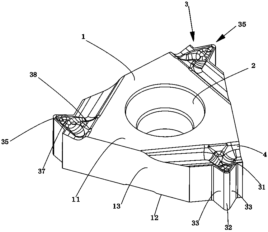
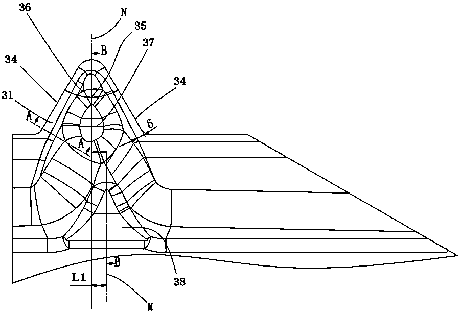
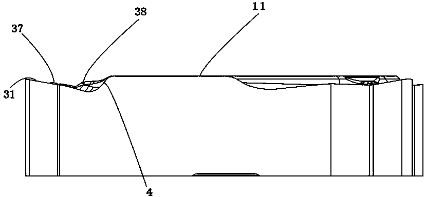
[0022] Figure 1 to Figure 5 Shown is a thread processing blade embodiment of the present invention, the thread processing blade includes a blade body 1, the blade body 1 is surrounded by an upper surface 11, a lower surface 12 and a side surface 13, and the blade body 1 is provided with a blade center hole 2 And the cutting edge portion 3, the cutting edge portion 3 is surrounded by a rake face 31, a rake face 32 and two bevel side faces 33, and the two bevel facets 33 intersect with the rake face 31 to form two side cutting edges 34, the angle between the two side cutting edges 34 is the cutting edge angle 35, the rake face 31 is connected with the upper surface 11 of the blade body 1 through a connecting curved surface 4, and the rake face 31 is provided with a cutting edge angle 35 The chip guide groove 36 is distributed symmetrically on the bisector of the angle N, protruding outward from the inside of the chip guide groove 36 to form a spherical chip breaking boss 37 hig...


PUM


Abstract

The invention discloses a thread machining blade which comprises a blade body. The blade body is provided with a blade center hole and cutting edge parts. Each cutting edge part is defined by a front blade surface, a cutting edge angle arc surface and two cutting edge angle side surfaces in an enclosed mode, wherein the two cutting edge angle side surfaces intersect with the front blade surface to form two side cutting edges, the included angle between the two side cutting edges is a cutting edge angle, the front blade surface is connected with the upper surface of the blade body through a connecting curved surface, the front blade surface is provided with a chip guiding groove which is arranged in a symmetric mode relative to the angular bisector N of the cutting edge angle, a spherical chip breaking boss higher than the front blade surface is formed in an outward protruding mode from the inside of the chip guiding groove, a triangular chip breaking boss is formed by extending from the connecting curved surface towards the inside of the chip guiding groove, and the triangular chip breaking boss is connected with the chip guiding groove in a circular arc transition mode. The thread machining blade has the advantages that machining is easy and fast, chips are low in friction in the flowing process, the degree of finish of a workpiece thread is high, the blade is high in strength, machining efficiency can be effectively improved, and production cost is lowered.

Description

technical field [0001] The invention relates to thread processing inserts, in particular to indexable thread processing inserts. Background technique [0002] Thread turning is special. During thread processing, the two cutting edges of each cutting edge corner of the thread insert participate in cutting at the same time and the feed rate is large. The chips become wider and wider with the increase of cutting depth, wide and hard. Chips are difficult to break and easily entangled on the workpiece, tool and fixture. The cutting edge angle of the threading insert is small and low in strength. The chips rotating at high speed with the workpiece are easy to hit the blade and cause chipping. The entanglement of the chip will also cause the workpiece The thread finish is degraded, and the entanglement of chips is also easy to cause danger to the operator. At the same time, when the threaded insert is processing plastic and viscous materials such as stainless steel, alloy material...

Claims


Application Information

Patent Timeline
IPC IPC(8): B23G5/00
Inventor 宋吉
Owner ZHUZHOU CEMENTED CARBIDE CUTTING TOOLS CO LTD
Why Eureka
Try Eureka