
Leak detector for blast furnace cooler

A technology of coolers and leak detectors, applied in the direction of inspection devices, etc., can solve the problems of no leakage point, hearth freezing, long time, etc., and achieve the effects of shortening detection time, accurate detection, and reducing labor intensity

Inactive Publication Date: 2014-03-19
XINYU IRON & STEEL CO LTD
View PDF5 Cites 9 Cited by
  • Summary
  • Abstract
  • Description
  • Claims
  • Application Information

AI Technical Summary

Problems solved by technology

If the water leakage of the blast furnace cooler cannot be detected and dealt with in time, it will seriously threaten the normal production of the blast furnace, greatly reduce the economic indicators of blast furnace production and the life of the furnace body, and even cause vicious accidents such as hearth freezing
Judging from the current situation, the blast furnace leak detection technology is basically still at the level of manual observation. When the furnace temperature, water temperature or gas is abnormal, see the plumber and close the water inlet valve. At this time, the gas pressure in the furnace is greater than the water pressure, and the coolers are opened one by one. Check whether there is obvious gas discharge in the water. If this happens, the water leakage of the cooler has seriously affected the production of the blast furnace.
Due to the lack of leak detection technology, leak detection experience and equipment, it takes a long time to find a leak point that is not obvious at the initial stage, or even no leak point can be found at all.
It is easy to be found only when the water leakage of the cooler is serious. There is currently no good detection method for the initial water leakage of the cooler

Method used


Image

  • Leak detector for blast furnace cooler
  • Leak detector for blast furnace cooler

Examples


Embodiment Construction

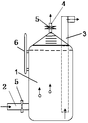
[0011] The present invention will be further described below in conjunction with accompanying drawing, see figure 2 , a blast furnace cooler leak detector, comprising a gas collection tank 1, the gas collection tank 1 is a transparent vessel, a water inlet pipe 2 and a valve 5 are installed below it, and an air outlet pipe 4 and a valve 5 are installed above the gas collection tank 1, Outlet pipe 3 is housed in the gas collection tank 1, and the water outlet of water outlet pipe 3 tops is higher than the air outlet of air outlet pipe 4, and the bottom of water outlet pipe 3 is positioned at the bottom of air collection tank 1.

[0012] A water level gauge 6 is installed on one side of the gas collecting tank 1 .

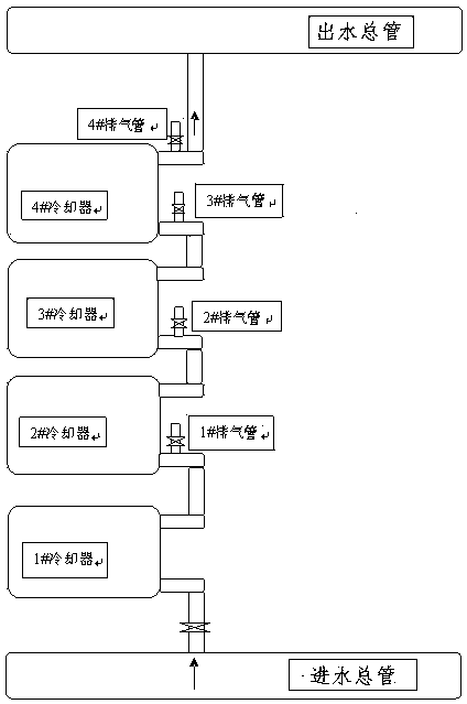
[0013] to combine figure 1 , during normal production of the blast furnace, connect the water inlet pipe 2 of the present invention with a flexible pipe on the exhaust pipe of each cooler, and the water outlet pipe 3 keeps the long-pass state. Open the valve on th...


PUM


Abstract

The invention discloses a leak detector for a blast furnace cooler. The leak detector comprises an air collecting tank which is a transparent vessel, wherein a water inlet pipe and a valve are arranged below the air collecting tank; an air outlet pipe and a valve are arranged on the upper part of the air collecting tank; a water outlet pipe is arranged inside the air collecting tank; a water outlet at the top of the water outlet pipe is higher than the air outlet of the air outlet pipe; the bottom end of the water outlet pipe is located at the bottom of the air collecting tank. By virtue of the leak detector, leak detection can be performed while a blast furnace is in normal production; with neither disconnecting of water nor damping down, but only through control on a small amount of water, whether gas exists in a pipeline can be visibly known by viewing whether air bubbles float up in the transparent air collecting tank, so that leak points can be rapidly and correctly detected, the detection time is shortened and the labor intensity of detecting workers is reduced.

Description

technical field [0001] The invention relates to an instrument for detecting water leakage of equipment, which is suitable for leak detection of coolers cooled by soft water closed circuit circulation, in particular to a blast furnace cooler leak detector. Background technique [0002] A blast furnace is an ironmaking shaft furnace with a circular cross section. The steel plate is used as the furnace shell, and the shell is lined with refractory bricks. A cooler is arranged between the furnace shell and the inner lining of the furnace waist, bosh and hearth, forming a circle to protect the furnace lining. The blast furnace cooler has two independent water channels in the inner layer and the outer layer, and the inner layer and the outer layer are provided with separate water inlets and outlets. Starting from the hearth upwards, a group of three to four coolers, see figure 1 . figure 1 It is a schematic diagram of the inner layer or outer layer of a group of coolers in sin...

Claims


Application Information

Patent Timeline
IPC IPC(8): C21B7/24
Inventor 莫云星张志荣孙武全叶建刚曾庆球伍强黄家彬黄振泰黄文平
Owner XINYU IRON & STEEL CO LTD
Learn More