
A modular combined electric boiler

An electric boiler and modular technology, applied in the field of modular combined electric boilers, can solve the problems of maintenance trouble, increase, waste of resources and economic costs, etc., and achieve the effects of simple and convenient connection, reduction of use costs, and avoidance of waste of resources.

Active Publication Date: 2016-08-17
北京老万清洁供暖设备有限责任公司 +1
View PDF9 Cites 0 Cited by
  • Summary
  • Abstract
  • Description
  • Claims
  • Application Information

AI Technical Summary

Problems solved by technology

[0003] At present, my country's traditional electric hot water heating boilers use rated power boilers or provide heating for fixed heating areas. Boilers with this structure can provide heating for small-area houses. Once the heating area and heating power increase or decrease At this time, the electric boiler cannot increase or decrease the rated power according to the increase or decrease of the heating area, which will cause the occurrence of insufficient heating or overheating of heating, so the boiler with this structure will not be able to meet people's needs in actual use. In order to solve the problem of insufficient heating, it is necessary to replace a high-power boiler or add another boiler appropriately. When the area decreases, in order to solve the discomfort caused by overheating, a small boiler must be replaced. Both of the above two situations will cause resource loss. In addition, once the boiler breaks down, it will stop heating people, which will seriously affect people's heating demand in cold winter during the long-term maintenance process. It is inconvenient to use and troublesome to maintain. It is not practical in actual use. sex

Method used


Image

  • A modular combined electric boiler
  • A modular combined electric boiler
  • A modular combined electric boiler

Examples


Embodiment Construction

[0021] The present invention will be described in further detail below through specific embodiments and in conjunction with the accompanying drawings.

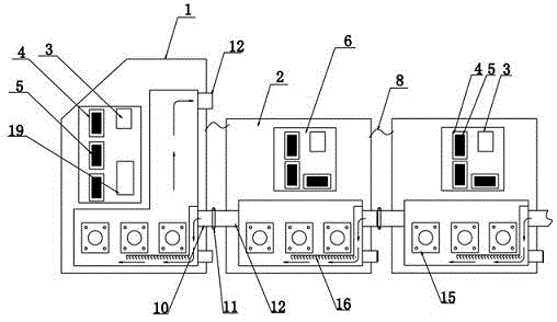
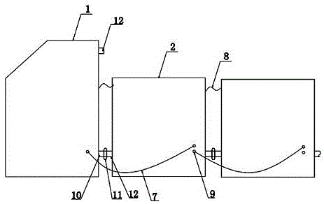
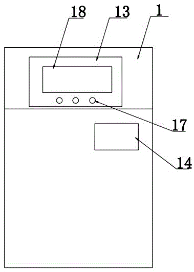
[0022] Such as figure 1 As shown in or 2, a modular combined electric boiler according to the embodiment of the present invention includes a main furnace body 1 and at least one auxiliary furnace body 2, and the main furnace body and the auxiliary furnace body are equipped with interconnected circuit equipment 6 and Water heat exchange system; the circuit equipment in the main furnace body and the auxiliary furnace body are connected through the data line 7, and the water heat exchange systems in the main furnace body and the auxiliary furnace body are connected to each other to form a circulating waterway.

[0023] In this technical solution, the modular combined electric boiler can manually increase or decrease the auxiliary furnace body according to the size of the heating area and heating power. The main furnace body can ...


PUM


Abstract

The invention discloses a modular combined electric boiler, which comprises a main furnace body and at least one auxiliary furnace body. The main furnace body and the auxiliary furnace body are both equipped with interconnected circuit equipment and a water heat exchange system; the main furnace body and the auxiliary furnace body The circuit equipment in the body is connected through data lines, and the water heat exchange systems in the main furnace body and the auxiliary furnace body are connected to each other to form a circulating water circuit. The beneficial effect of the present invention is: the modular combined electric boiler provided by the present invention can manually increase or decrease the auxiliary furnace body according to the size of the heating area and heating power, and the auxiliary furnace body can be increased freely like stacking wood. Combination, to meet the personalized heating demand, through the control system in the main furnace body, the opening and closing of the solid state relay in the auxiliary furnace body can be adjusted, so as to adjust the heating power of the whole boiler, avoiding the waste of resources, when one of the auxiliary furnace body appears In case of failure, the maintenance is only to stop the circuit equipment of the furnace body without affecting the overall heating, which is practical.

Description

technical field [0001] The invention relates to the technical field of heating equipment, in particular to a modular combined electric boiler. Background technique [0002] With the continuous improvement of people's living standards, electric boilers are constantly being used in cold winters. Compared with other heating facilities, electric boilers have the advantage of not polluting the environment, not emitting harmful smoke and a large amount of slag, and reducing the number of operators. In addition, it is small in size, saves floor space, and can realize automatic control. Therefore, the use of electric boilers is becoming more and more popular. [0003] At present, my country's traditional electric hot water heating boilers use rated power boilers or provide heating for fixed heating areas. Boilers with this structure can provide heating for small-area houses. Once the heating area and heating power increase or decrease At this time, the electric boiler cannot increas...

Claims


Application Information

Patent Timeline
Patent Type & Authority Patents(China)
IPC IPC(8): F24H1/22F24H9/20F24H9/00
Inventor 贺仁平
Owner 北京老万清洁供暖设备有限责任公司
Learn More