
Solar trough concentrating system

A trough concentrating system, solar energy technology, applied in solar heating systems, solar thermal energy, solar thermal power generation and other directions, can solve the problems of large rotation radius, large consumption, increase the complexity of the transmission system, etc., to simplify the tracking method, reduce cost effect

Active Publication Date: 2015-12-09
INST OF ELECTRICAL ENG CHINESE ACAD OF SCI
View PDF8 Cites 0 Cited by
  • Summary
  • Abstract
  • Description
  • Claims
  • Application Information

AI Technical Summary

Problems solved by technology

In fact, this kind of structure is difficult to realize. Since the heat collecting tube coincides with the center of rotation, it will inevitably cause interference between the heat collecting tube and the support point of the solar trough heat collecting device. In order to ensure that the heat collecting device has sufficient rigidity, its span can only be Made small, at the same time, the device supporting the collector tubes creates a discontinuity in the reflective surface
In addition, when the solar heat collector rotates around the heat collector tube, the radius of rotation will be large, which increases the complexity of the transmission system and brings greater consumption

Method used


Image

  • Solar trough concentrating system
  • Solar trough concentrating system

Examples


Embodiment Construction

[0015] The present invention will be further described below in conjunction with the accompanying drawings and specific embodiments.

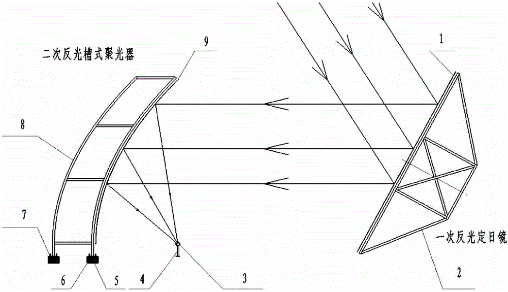
[0016] figure 1 Shown is a schematic diagram of the solar trough concentrating system of the present invention, the system is composed of a primary reflective heliostat, a secondary reflective trough concentrator and a vacuum heat-absorbing tube 3, arranged sequentially from south to north, the order is: secondary Reflective trough concentrator, vacuum heat absorbing tube 3, and primary reflective heliostat are independent of each other. The primary reflective heliostat can be an array composed of multiple dual-axis tracking heliostats, or a single-axis tracking heliostat with a large aspect ratio that matches the secondary reflector trough concentrator.

[0017] The primary reflector heliostat is composed of a flat silver-plated reflector 1 with high reflectivity, a primary reflector bracket 2 and a tracking control system. The flat silver-c...


PUM


Abstract

The invention provides a groove-type solar light condensing system which is formed by a primary reflection heliostat, a secondary reflection groove-type solar light condenser and a vacuum heat absorbing tube (3). The primary reflection heliostat is arranged in a lined mode in the east and west direction, tracks the sun around the clock, always reflects solar rays onto the secondary reflection groove-type solar light condenser and ensures that the solar rays are parallel to the symmetric center plane of the secondary reflection groove-type solar light condenser. The secondary reflection groove-type solar light condenser focuses the parallel rays from the primary reflection heliostat on the vacuum heat absorbing tube (3). According to the groove-type solar light condensing system, the secondary reflection groove-type solar light condenser and the vacuum heat absorbing tube (3) are immobilized in the working process.

Description

technical field [0001] The invention relates to a solar trough-type concentrating device. Background technique [0002] The energy crisis is becoming increasingly prominent worldwide, and renewable energy will become an important part of the world's energy structure in the future. Especially, it is of great significance to the rational development of solar energy utilization. In recent years, scientific researchers from various countries in the world have carried out a lot of work and scientific exploration in this area, and have achieved certain results. Solar thermal power generation is the most typical representative. At present, the forms of solar thermal power generation system mainly include: solar tower type, solar trough type, solar dish type and solar Fresnel type and so on. Among them, the solar trough concentrating system is the main form of solar thermal power generation adopted in recent years. It is the earliest form of solar thermal power generation to achi...

Claims


Application Information

Patent Timeline
Patent Type & Authority Patents(China)
IPC IPC(8): F24J2/10F24J2/05F24J2/24F24S23/70F24S10/40F24S10/70
CPCY02E10/44
Inventor 张喜良王志峰
Owner INST OF ELECTRICAL ENG CHINESE ACAD OF SCI
Learn More