Grooved wheel compensation device

A compensating device and sheave technology, applied in the direction of overhead lines, etc., can solve the problems of complex installation on the construction site, high manufacturing process requirements, and insufficient braking effect, so as to improve the installation speed and installation quality, and the braking effect is good. Effect of short braking distance

Inactive Publication Date: 2017-06-16
YANGZHOU DONGFANG HANGER FRAME CO LTD
View PDF12 Cites 3 Cited by
  • Summary
  • Abstract
  • Description
  • Claims
  • Application Information

AI Technical Summary

Problems solved by technology

[0005] The shortcomings of a "compensating device with pulleys for adjusting devices" are: the device has insufficient braking effect, high manufacturing process requirements, and complicated installation on the construction site, etc.
[0007] The shortcomings of a "side brake ratchet tension compensation device for electrified railway catenary" are: the device has insufficient braking effect, high manufacturing process requirements, and complicated installation on the construction site, etc.
[0009] The disadvantages of a "bevel gear ratchet compensation device" are: the braking effect of the device is not obvious enough, the manufacturing process requirements are high, and the installation on the construction site is complicated, etc.
[0011] ] The shortcomings of a "new ratchet compensation device" are: the braking effect of the device is not obvious enough, the manufacturing process is high, and the installation on the construction site is complicated.
[0013] The shortcomings of a "ratchet compensation mechanism and design method for electrified railway catenary" are: the braking effect of the device is not obvious enough, the manufacturing process requirements are high, and the installation on the construction site is complicated, etc.

Method used


Image

  • Grooved wheel compensation device
  • Grooved wheel compensation device
  • Grooved wheel compensation device

Examples


Embodiment 1

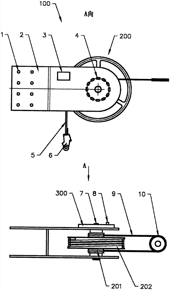
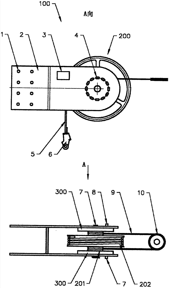
[0036] In Embodiment 1, a built-in brake 300 is installed on one side of the connecting frame 2, which at least includes a connecting hole 1, a connecting frame 2, a nameplate 3, a locking hole 4, a steel wire rope 5, double ear wedge clamps 6, a main shaft 7, a locking pin 8, and a steel wire rope 9 , balance wheel 10, wheel body 200 and brake 300 are formed.

[0037] In Embodiment 1, the wire rope 5 is wound and fixed in the wire groove of the large circle 201 of the wheel body 200; one end of the wire rope 9 is fixed and wound in the wire groove of the small circle 202 of the wheel body 4, and the other end of the wire rope 9 is connected to the balance wheel 10 Then wind in the other side wire groove of the small circle 202 of the wheel body 200 in turn. Catenary conductors (carrying cables and catenary wires) produce thermal expansion and contraction under the influence of ambient temperature, through the synchronous operation of the small circle 201 of the upper wheel bo...

Embodiment 2

[0051] In Embodiment 2, an external brake 300 is installed on one side of the connecting frame 2 , which is the second way of installing the brake 300 on the sheave compensation device 100 . The difference from Embodiment 1 is that the brake 300 is arranged outside the connecting frame 2 .

Embodiment 3

[0052] In Embodiment 3, built-in brakes 300 on both sides of the connecting frame 2 are the third way of installing the brakes 300 in the sheave compensation device 100 . The difference from Embodiment 1 is that two brakes 300 are installed inside the connecting frame 2 at the same time. This Embodiment 3 is suitable for a sheave compensation device 100 with a rated tension greater than 30-60 kN.


PUM


Abstract

The invention relates to the technical field of electrified railway power supply, in particular relates to a grooved wheel compensation device 100 used by the anchor compensation of electrified railway contact line guide wire (carrier cable and contact wire). The compensation device comprises a connecting hole 1, a connecting frame 2, a nameplate 3, a locking wire hole 4, a steel wire rope 5, a double ear wedge-shape clamp 6, a spindle 7, a locking pin 8, a steel wire rope 9, a balance wheel 10, a wheel body 200 and a braking device 300. The steel wire rope 5 is connected with a weighing mound through the double ear wedge-shape clamp 6, the steel wire rope 9 and the balance wheel 10 through an insulator are connected with the contact line guide wire (carrier cable and contact wire). The high speed electrified railway contact line guide wire (carrier cable and contact wire) can instantly brake when disconnection accidents occur, the braking effect is good and the braking distance is short, meanwhile, the device is provided with the tension lock and 60kN above carrying capacity.

Description

technical field [0001] The invention relates to the technical field of electrified railway power supply. In particular, the utility model relates to a sheave compensating device used for anchor compensation of catenary conductors (catchers and catenary wires) of electrified railways. Background technique [0002] The electric railway catenary wire (catcher and contact wire) will expand with heat and contract with cold due to the influence of ambient temperature changes. Anchor compensation device to compensate for its variation. [0003] The existing electrified railway catenary wire (catcher and catenary) anchor compensation device generally adopts a ratchet compensation device. [0004] In the Chinese patent database, a publication specification for a "compensating device with pulleys for adjustment device" patent application has been published, its publication number: CN 1285292 A, application date: 2000.6.21, publication date: February 28, 2001, Applicant: (Germany) S...

Claims


Application Information

Patent Timeline
Patent Type & Authority Applications(China)
IPC IPC(8): B60M1/26
CPCB60M1/26
Inventor 帖荣俊吴利群帖荣康帖广宏吴承宸帖广智
Owner YANGZHOU DONGFANG HANGER FRAME CO LTD
Why Eureka
Try Eureka