
Air pressure sensor testing method and testing system for brake system

A technology of air pressure sensor and braking system, which is applied in the direction of instruments, measuring devices, and measuring fluid pressure, etc. It can solve the problems that the test is not simple, convenient and efficient, and the test and calibration of the air pressure sensor is not intuitive and accurate enough, so as to achieve intuitive testing , test reliability, great social significance and the effects of marketing value

Inactive Publication Date: 2017-01-11
HUBEI UNIV OF AUTOMOTIVE TECH
View PDF5 Cites 0 Cited by
  • Summary
  • Abstract
  • Description
  • Claims
  • Application Information

AI Technical Summary

Problems solved by technology

[0004] The present invention aims to solve the problems that the relevant testing and calibration of the air pressure sensor of the existing brake system is not intuitive enough, accurate enough, and the testing is not simple enough, convenient and low in efficiency, and proposes a simple and convenient operation, intuitive and accurate testing, reliable testing and high efficiency. Air pressure sensor test method and test system of Gaode brake system

Method used


Image

  • Air pressure sensor testing method and testing system for brake system
  • Air pressure sensor testing method and testing system for brake system
  • Air pressure sensor testing method and testing system for brake system

Examples


Embodiment Construction

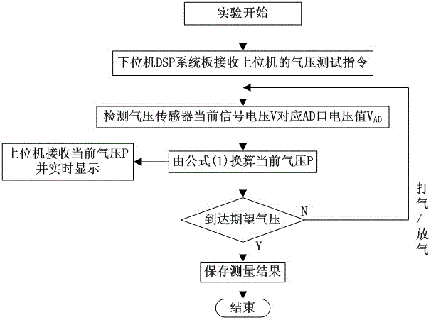
[0024] The air pressure sensor testing method of the braking system of the present invention first calibrates the air pressure sensor to obtain the calibration relationship between the current air pressure P and the current sensor signal voltage V corresponding to the voltage value VAD of the AD port, and then performs the test according to the operator's desired air pressure. Inflate or deflate. During the inflate / deflate process, observe the current air pressure through the pressure gauge, car air pressure gauge and host computer virtual air pressure gauge. When the desired air pressure is reached, measure and save the measurement results.

[0025] The calibration process of the air pressure sensor in the air pressure sensor testing method of the braking system of the present invention is as follows:

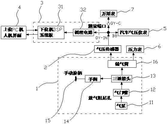
[0026] Such as Figure 4 , 5 As shown, first connect the air pressure sensor signal as a resistance related to air pressure to the terminal B8 of the automobile air pressure ...


PUM


Abstract

The invention relates to a gas pressure sensor test method for a braking system and a test system thereof. The test method comprises the following steps: calibrating the coefficient of a gas pressure sensor to acquire a calibration relation between the current gas pressure P and a current sensor signal voltage V corresponded AD port voltage value VAD, conducting gas inflating or gas discharge according to an expected gas pressure, and observing the current gas pressure, carrying out measuring when the expected gas pressure is reached and saving the measuring result. The test system includes: an upper PC human-computer interface, a lower computer unit and the gas pressure sensor. The lower computer unit is connected to the upper PC human-computer interface through a lower computer DSP system board and is connected to the gas pressure sensor through a conditioning circuit, which is formed by connection of an operational amplifier U1, an operational amplifier U2, a resistor R21, a resistor R22 and a capacitor C21. The test method provided by the invention has the advantages of simple and convenient operation, scientific and precise measurement, high measurement efficiency and good effect. The test system provided by the invention has the characteristics of simple and reasonable structural design, visual and precise testing and calibration, stable and reliable use, and high test efficiency.

Description

technical field [0001] The invention relates to the technical field of an air pressure sensor of an automobile brake system, in particular to a method for testing an air pressure sensor of a brake system and a test system thereof. Background technique [0002] According to incomplete statistics, in the traffic accidents caused by the problems of the vehicle itself, the traffic accidents caused by the failure of the braking system account for 45% of the total. The U.S. Federal Highway Transportation Safety Administration statistics on traffic accidents caused by non-human factors show that about one-third of road safety accidents are caused by vehicle braking system failure or poor braking. At present, most of the brake system research is the development and performance analysis of the brake system development platform. In the late 1990s, Japanese companies such as Toyota and Isuzu have begun to study the brake system development platform and achieved certain results. In rec...

Claims


Application Information

Patent Timeline
Patent Type & Authority Patents(China)
IPC IPC(8): G01L27/00
Inventor 程登良黄海波王卫华张凯蒋伟荣黄志文
Owner HUBEI UNIV OF AUTOMOTIVE TECH
Learn More