Flow frame assembly and flow battery

A technology of flow battery and flow frame, applied in fuel cells, regenerative fuel cells, fuel cell grouping, etc., can solve the problems of low energy efficiency and large bypass current loss, so as to improve current efficiency and reduce bypass current. , the effect of increasing the flow path

Active Publication Date: 2016-03-02
DONGFANG ELECTRIC (CHENGDU) HYDROGEN FUEL CELL TECH CO LTD
View PDF4 Cites 0 Cited by
  • Summary
  • Abstract
  • Description
  • Claims
  • Application Information

AI Technical Summary

Problems solved by technology

[0004] The present invention aims to provide a flow frame assembly and a flow battery to solve the problems of large bypass current loss and low energy efficiency in the flow battery in the prior art

Method used


Image

  • Flow frame assembly and flow battery
  • Flow frame assembly and flow battery
  • Flow frame assembly and flow battery

Examples


Embodiment Construction

[0026] The embodiments of the present invention will be described in detail below with reference to the accompanying drawings, but the present invention can be implemented in many different ways defined and covered by the claims.

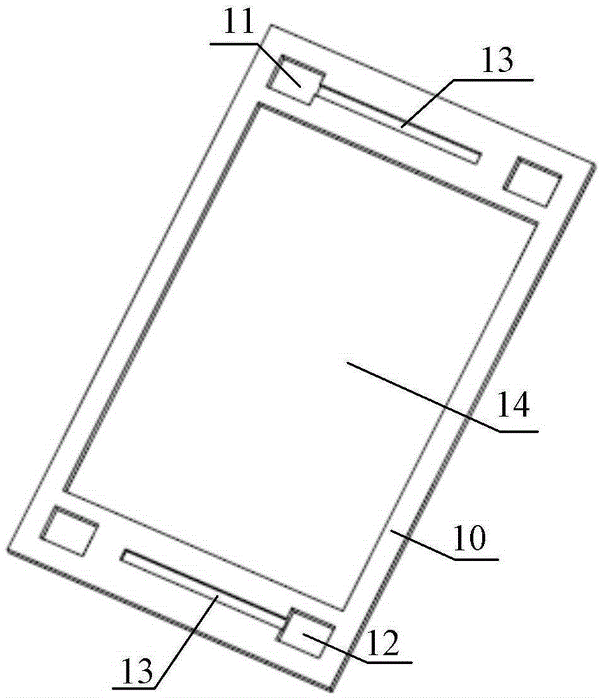
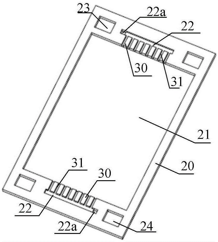
[0027] As a first aspect of the present invention, a liquid flow frame assembly is provided. like Figure 1 to Figure 4 As shown, the liquid flow frame assembly includes a plurality of stacked bodies, each of which has a flow channel section, and the flow channel sections of the multiple bodies are sequentially connected end to end to form a flow channel. Since the flow channel sections on the stacked bodies are connected end to end in order to form a flow channel, after the electrolyte flows into the liquid flow frame assembly from the main pipe, it needs to flow through multiple flow channel sections in sequence before reacting with the electrodes, thereby The liquid flow path of the electrolyte is increased, thereby reducing the bypass current a...


PUM


Abstract

The invention provides a flow frame component and a flow battery. The flow frame component comprises a plurality of superimposed bodies, wherein each body is provided with a flow channel section; and the flow channel sections of the bodies are sequentially communicated end to end to form a flow channel. Since the flow channel sections of the bodies are sequentially communicated end to end to form the flow channel, the electrolyte needs to sequentially flow across the plurality of flow channel sections and then react with the electrode after flowing into the flow frame component from the main pipeline, thereby increasing the flow path of the electrolyte, further lowering the bypass current and enhancing the current efficiency of the flow battery system. Meanwhile, the flow frame component has the characteristics of simple structure and low manufacturing cost.

Description

technical field [0001] The present invention relates to the technical field of flow batteries, and more specifically, to a flow frame assembly and a flow battery. Background technique [0002] A flow battery stack in the prior art includes a plurality of flow batteries stacked one after the other. [0003] The liquid flow battery in the prior art includes an ion exchange membrane, an electrode, a flow frame and a bipolar plate, the electrode is arranged in the reaction opening of the flow frame, and the electrode and the flow frame are located between the ion exchange membrane and the bipolar plate Between, the flow channel of the liquid flow frame is set towards the side of the ion exchange membrane. When the liquid flow battery is working, the electrolyte needs to flow into the reaction opening through the flow channel. The liquid flow battery in the prior art has the problems of large bypass current loss and low energy efficiency. Contents of the invention [0004] T...

Claims


Application Information

Patent Timeline
Patent Type & Authority Patents(China)
IPC IPC(8): H01M8/02H01M8/24H01M8/0258
CPCH01M8/0273H01M8/18Y02E60/50
Inventor 殷聪汤浩宋彦彬李扬
Owner DONGFANG ELECTRIC (CHENGDU) HYDROGEN FUEL CELL TECH CO LTD
Why Eureka
Try Eureka