

Comprehensive power transmission line video monitoring device based on LTE technology
A technology for power transmission line and comprehensive monitoring, applied in CCTV systems, instruments, burglar alarms, etc., can solve the problem of inability to realize real-time monitoring of power line equipment, and achieve the effect of convenient distinction and recording and high resolution
- Summary
- Abstract
- Description
- Claims
- Application Information
AI Technical Summary
Problems solved by technology
Method used
Image

Examples
Embodiment 1
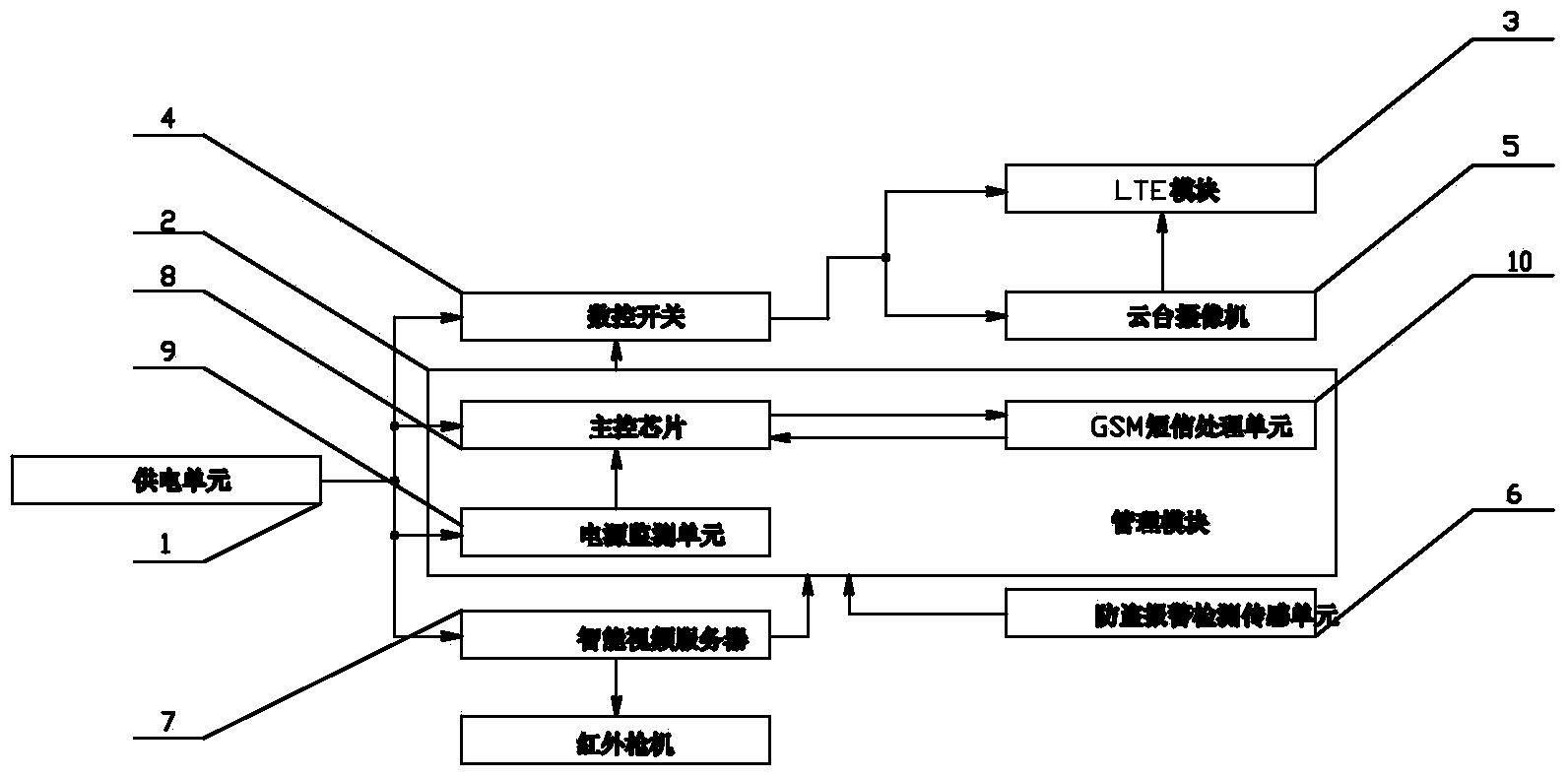
[0021] Embodiment 1: as figure 1 As shown, the LTE technology-based power transmission line video comprehensive monitoring device of the present invention includes a power supply unit 1, an intelligent video server 7, a management module 2, an LTE module 3, a numerical control switch 4, a pan-tilt camera 5 and an anti-theft alarm detection sensor. Sense unit 6, management module 2 comprises main control chip 8, GSM short message processing unit 10 and power monitoring unit 9, GSM short message processing unit 10 and power monitoring unit 9 are respectively connected to main control chip 8 signal input ends, main control chip 8 power supply Terminal and power supply monitoring unit 9 power supply terminals are connected to power supply unit 1 through power supply monitoring unit 9 power supply terminals, one end of digital control switch 4, the power supply terminal of power supply monitoring unit 9 and the power supply terminal of intelligent video server 7 are all connected to...
Embodiment 3
[0022] Embodiment 3: On the basis of the structure of Embodiment 2, the anti-theft alarm detection sensing unit 6 includes an infrared sensor and a vibration sensor, both of which are connected to the management module 2 through a communication line.
[0023] Operation steps and working principle:
[0024]When the infrared sensor or the shock sensor of the anti-theft alarm detection sensing unit 6 or the intelligent video server detect that someone intends to destroy the power facility, an alarm signal will be sent to the main control chip 8 in the management module 2, and the main control chip in the management module 2 will 8. After receiving the alarm signal, the numerical control switch 4 will be triggered to be turned on. After the numerical control switch 4 is turned on, the camera 5 will be powered, and the camera 5 will start recording. The recorded high-definition video images will be sent to the monitor through the LTE module 3. After receiving the video signal, the ...
PUM
 Abstract
Description
Claims
Application Information