Imaging system detector calibration

一种探测器、探测器阵列的技术,应用在仪器、测量装置、科学仪器等方向,能够解决不太适合校准等问题

Active Publication Date: 2014-03-19
KONINKLIJKE PHILIPS NV
View PDF8 Cites 8 Cited by
  • Summary
  • Abstract
  • Description
  • Claims
  • Application Information

AI Technical Summary

Problems solved by technology

As such, conventional methods for calibrating the gain of conventional scintillators, such as the exemplary method discussed above in which the gain is recalibrated approximately monthly, are not well suited to be used to calibrate the gain of such materials

Method used


Image

  • Imaging system detector calibration
  • Imaging system detector calibration
  • Imaging system detector calibration

Examples


Embodiment Construction

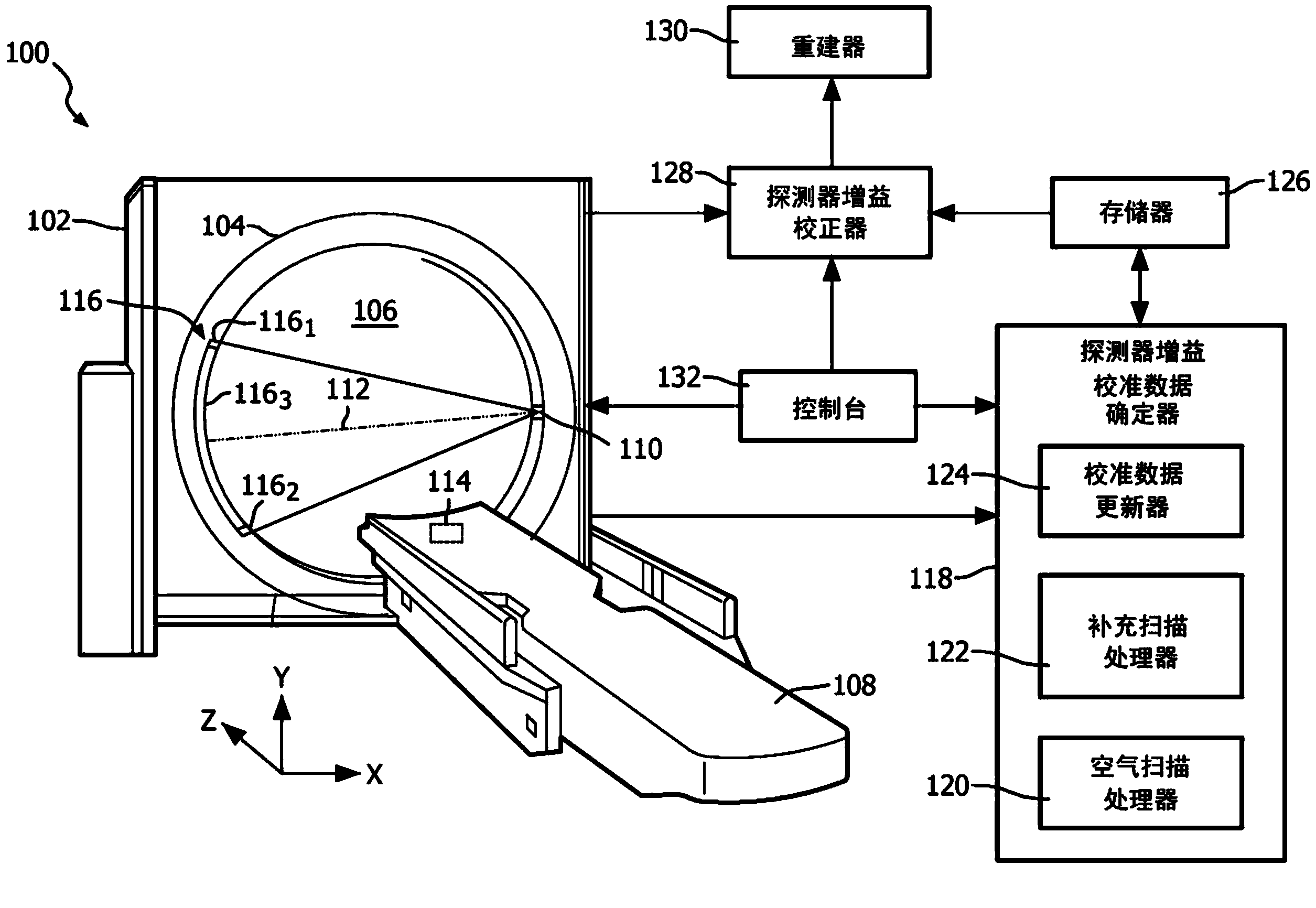
[0022] figure 1 An imaging system 100 is illustrated, such as a computed tomography (CT) scanner

[0023] The imaging system 100 includes a fixed gantry 102 and a rotating gantry 104 rotatably supported by the fixed gantry 102 . The rotating gantry 104 is configured to rotate about an examination region 106 about a longitudinal or z-axis.

[0024] A subject support 108 , such as a couch, supports an object or subject in the examination region 106 and positions the object or subject with respect to x, y and / or z axes before, during and / or after scanning.

[0025] Primary source 110 , such as an X-ray tube, is supported by rotating gantry 14 and rotates about examination region 106 in coordination with rotating gantry 104 . Primary source 110 emits a generally fan-shaped, cone-shaped, or wedge-shaped beam of radiation that travels along path 112 from one side of examination region 106 to the other. Primary source 110 is used to perform conventional air scans or object or subj...


PUM


Abstract

A system (100) includes a stationary gantry (102) and a rotating gantry (104), wherein the rotating gantry is rotatably supported by the stationary gantry. The rotating gantry (104) includes a primary source (110) that emits primary radiation and a detector array (116) having at least one row of detector elements (502) extending along a longitudinal axis. The primary source and the detector array are located opposite each other, across an examination region, and the primary radiation traverses a path (112) between the primary source and the detector array and through an examination region (106) and illuminates the at least one row of detector elements of the detector array, which detects the primary radiation. The system further includes a supplemental source (114), wherein the supplemental source is affixed to a non-rotating portion of the system and emits radiation that traverses a sub-portion of the path and illuminates the at least one row of detector elements of the detector array, which detects the secondary radiation.

Description

technical field [0001] The following generally relates to the calibration of radiation sensitive detectors of X-ray based imaging system detector arrays and is described for the specific application of computed tomography (CT); however, the following applies to other X-ray based imaging systems as well. Background technique [0002] A CT scanner generally includes an X-ray tube supported by a rotating gantry that is rotatably attached to a stationary gantry. The X-ray tube emits radiation through the examination region and the object or part of the subject therein. A subject support positions the object or subject in the examination region for scanning. A radiation sensitive detector array is positioned opposite the examination region, on opposite sides of the x-ray tube, and includes a plurality of detector elements that detect radiation passing through the examination region and generate radiation indicative of the detected Radiant projection data. The projection data m...

Claims


Application Information

Patent Timeline
Patent Type & Authority Applications(China)
IPC IPC(8): A61B6/03
CPCA61B6/4233A61B6/4007A61B6/032G01N23/046A61B6/585G01T1/249G01T7/005
Inventor R·卡尔米
Owner KONINKLIJKE PHILIPS NV
Why Eureka
Try Eureka