
System with battery charging device and vehicle electrical system power supply stage

A technology for battery charging and vehicle power supply, applied in the field of voltage source systems, can solve problems such as expensive and non-optimal

Active Publication Date: 2014-03-19
ROBERT BOSCH GMBH
View PDF5 Cites 3 Cited by
  • Summary
  • Abstract
  • Description
  • Claims
  • Application Information

AI Technical Summary

Problems solved by technology

In particular in the case of large input and / or output voltage ranges, DC voltage converters of battery charging systems may often not be designed over the entire voltage matching range, so that such DC voltage converters are either expensive to operate with this design, or not working optimally

Method used


Image

  • System with battery charging device and vehicle electrical system power supply stage
  • System with battery charging device and vehicle electrical system power supply stage
  • System with battery charging device and vehicle electrical system power supply stage

Examples


Embodiment Construction

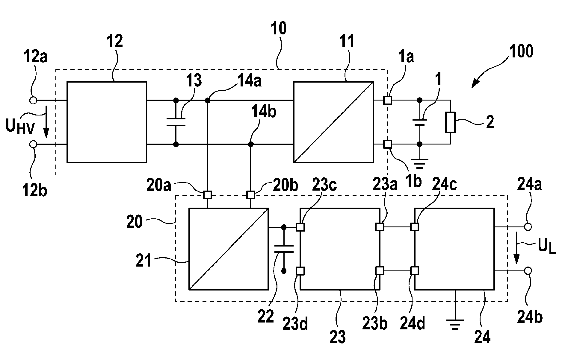
[0026] figure 1 A schematic diagram of a system 100 with a battery charging device 20 and an on-board power supply stage 10 that can supply, for example, a 12V on-board power supply is shown. The on-board power supply stage 10 can have an on-board power DC-voltage converter 11 , a DC-voltage intermediate circuit 13 and a step-up / step-down converter 12 . An input voltage U can be applied at the input terminals 12a, 12b of the vehicle power supply stage 10 HV , for example from the input voltage of the intermediate circuit of a high-voltage power source, eg a traction battery of an electrically operated vehicle, such as a hybrid vehicle or an electric vehicle. Input voltage U HV For example, it can be between 50 V and 500 V and can be boosted by the step-up / down converter 12 . Here, the boost / buck converter 12 can convert the input voltage U HV For example boost 25V.

[0027] exist figure 2 In , an exemplary configuration of the boost / buck converter 12 is shown schematica...


PUM


Abstract

The invention relates to a system (100) with a battery charging device (20) with output terminals and a vehicle electrical system power supply stage (10). The vehicle electrical system power supply stage has a step-up / step-down converter (12), which is designed to raise an input voltage of the vehicle electrical system power supply stage to an intermediate circuit voltage, a direct current intermediate circuit (13), which is coupled to the step-up / step-down converter (12) at intermediate circuit nodes (14a, 14b), and a vehicle electrical system d.c.-d.c. converter (11), which is coupled to the direct voltage intermediate circuit at the intermediate circuit nodes, and which is designed to convert the intermediate circuit voltage into a direct voltage for a vehicle electrical system (1, 2), the output terminals of the battery charging device (20) being coupled to the direct voltage intermediate circuit (13) via the intermediate circuit nodes (14a, 14b).

Description

technical field [0001] The invention relates to a system, in particular for a voltage source of an on-board power supply of an electrically operated vehicle, having a battery charging device and an on-board power supply stage with a common step-up / down converter. Background technique [0002] A DC power converter for an on-board power supply of an electrically operated vehicle often consists of a potential-isolated DC voltage converter and an upstream matching stage, so that the DC voltage converter can be used optimally. Especially in the case of a galvanically decoupled DC-to-voltage converter, it is advantageous for optimal operation of the DC-to-voltage converter to operate with a constant voltage ratio between the input voltage and the output voltage, so that the circuit only has to Being designed for a relatively small operating voltage range makes it possible to design components for current decoupling, such as transformers, cost-effectively. [0003] Battery chargin...

Claims


Application Information

Patent Timeline
Patent Type & Authority Applications(China)
IPC IPC(8): H02J7/00
CPCH02J7/0003B60L11/1811B60L53/20H02J7/00047Y02T10/70Y02T10/92Y02T10/7072Y02T90/14
Inventor E.魏森博恩J.法斯纳赫特
Owner ROBERT BOSCH GMBH
Learn More