Robot cleaner driving wheel mechanism

A technology for cleaning robots and driving wheels, applied to cleaning equipment, machine parts, vacuum cleaners, etc., can solve the problems of large turning radius, labor-saving, high cost, etc., and achieve the effect of small turning radius, easy steering and simple structure

Inactive Publication Date: 2014-03-26
光荣电业(东莞)有限公司
View PDF5 Cites 6 Cited by
  • Summary
  • Abstract
  • Description
  • Claims
  • Application Information

AI Technical Summary

Problems solved by technology

[0002] At present, there are two situations for the driving wheels of cleaning robots on the market: one is driven by two independent motors, and the second is driven by a single motor; the first driving method uses two motors, and this method controls the circuit Complicated and costly; when the second driving method turns, one driving wheel does not move while the other rotates around it. Although the second driving method is driven by a single motor, the left and right driving wheels do not rotate at the same time when turning, and cannot form a rotational couple , the turning radius is large, not labor-saving

Method used


Image

  • Robot cleaner driving wheel mechanism
  • Robot cleaner driving wheel mechanism
  • Robot cleaner driving wheel mechanism

Examples


Embodiment Construction

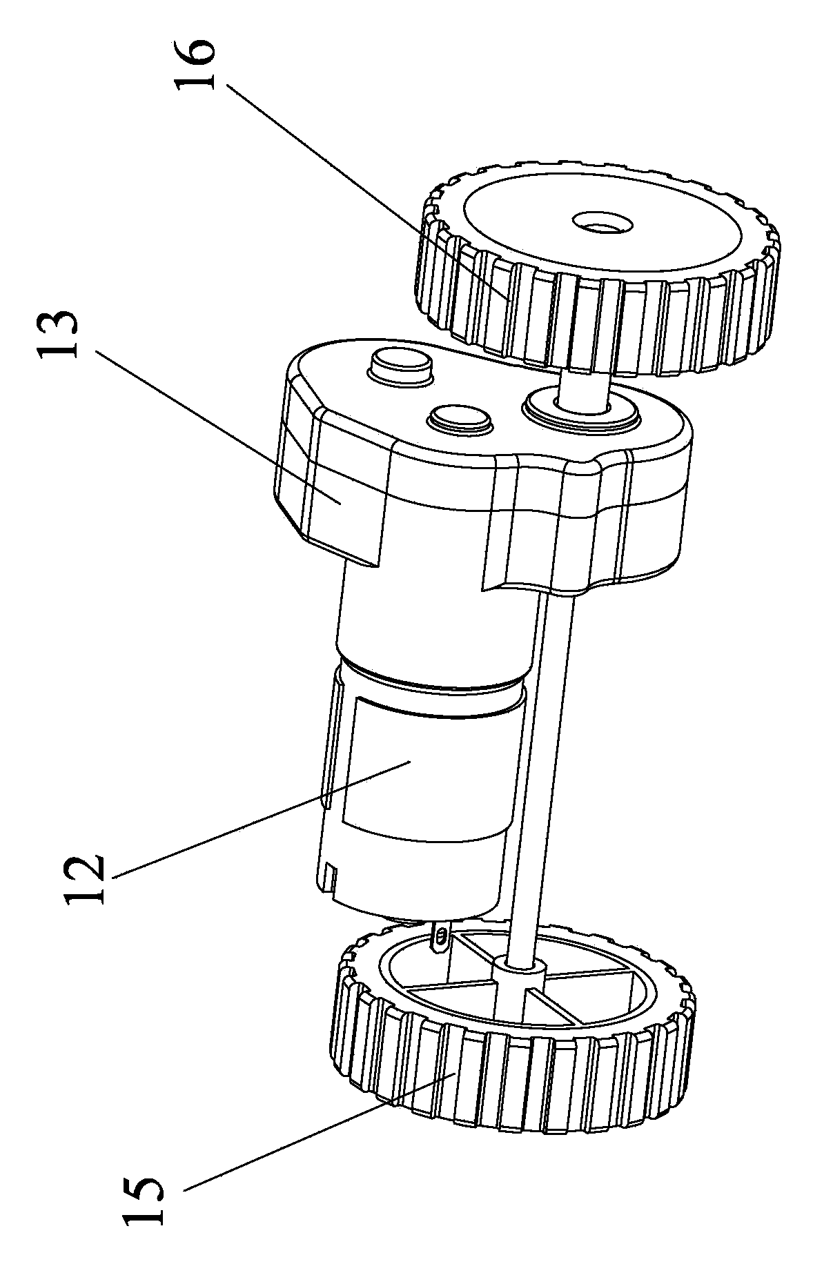
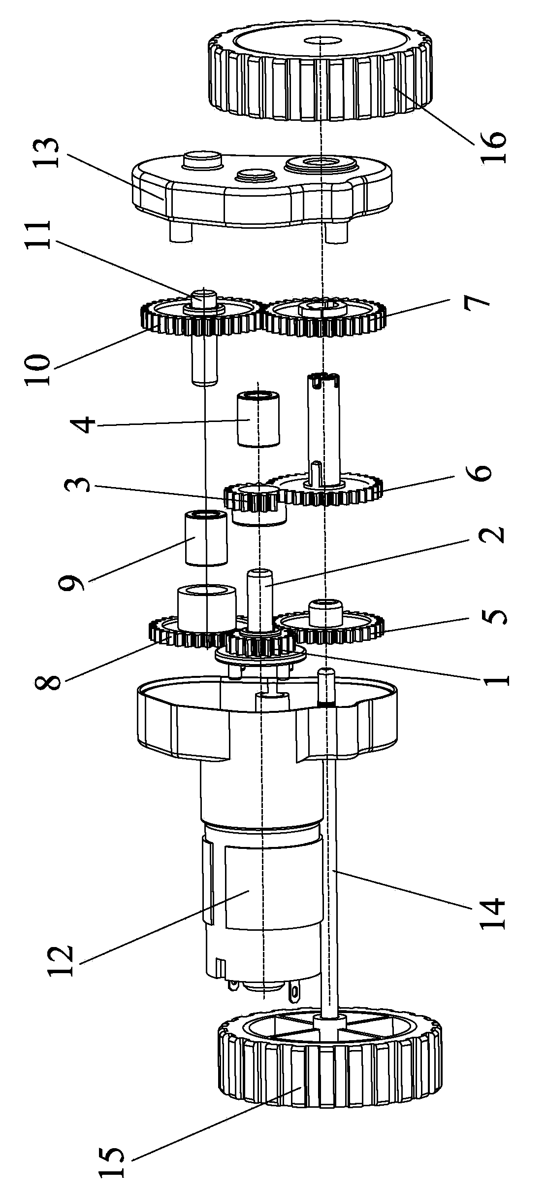
[0016] Such as Figure 1 to Figure 6 As shown, the driving wheel mechanism of the cleaning robot of the present invention includes a motor 12, a left driving wheel 15, a right driving wheel 16 and a gear box 13 connected with the motor 12. The first one-way bearing 4 and the second one-way bearing 4 are housed in the gear box 13. Bearing 9, one-way bearing can work in self-locking and free state respectively. Through the forward and reverse rotation of the motor and the control of the one-way bearing, the left and right drive wheels can work in different directions. Such as figure 2 As shown, one end of the gearbox 13 is provided with an output gear 1 of the motor 12, and the output gear 1 is closely matched with a shaft 2, and the outer edge of the shaft 2 is provided with a first one-way bearing 4, and the first one-way bearing 4 is tightly fitted. Fitted with a third gear 3, the output gear 1 transmits torque to the third gear 3 through the first one-way bearing 4; the o...


PUM


Abstract

The invention discloses a robot cleaner driving wheel mechanism which comprises a motor, a left driving wheel, a right driving wheel and a gear case connected with the motor. A first one-way bearing and a second one-way bearing are arranged in the gear case, and the first one-way bearing and the second one-way bearing both can work in a self-locking state and a free state. Through forward and backward rotation of the motor and control of the first one-way bearing and the second one-way bearing, the left driving wheel and the right driving wheel can rotate in different rotation directions. The robot cleaner driving wheel mechanism is simple in structure, reliable, low in cost, economical and practical. Due to the fact that the two driving wheels can rotate and turn at the same time, the rotation radius is small, resistance is low, and turning is easier. The driving wheel mechanism can be applied to various robot sweepers or dust collectors or similar cleaning machines.

Description

technical field [0001] The invention relates to a drive wheel mechanism, in particular to a drive wheel mechanism for a cleaning robot that saves labor when rotating, has simple control circuits, and is low in cost. Background technique [0002] At present, there are two situations for the driving wheels of cleaning robots on the market: one is driven by two independent motors, and the second is driven by a single motor; the first driving method uses two motors, and this method controls the circuit Complicated and costly; when the second driving method turns, one driving wheel does not move while the other rotates around it. Although the second driving method is driven by a single motor, the left and right driving wheels do not rotate at the same time when turning, and cannot form a rotational couple , The turning radius is large, not labor-saving. Contents of the invention [0003] In view of this, the main purpose of the present invention is to provide a driving wheel m...

Claims


Application Information

Patent Timeline
Patent Type & Authority Applications(China)
IPC IPC(8): A47L11/40A47L9/00
Inventor 赵仲伟
Owner 光荣电业(东莞)有限公司
Why Eureka
Try Eureka