
Catalytic purification and heat exchange system

A heat exchange system and catalytic purification technology, applied in the field of heat exchange, can solve problems such as waste and poor denitration effect, and achieve the effects of reducing energy consumption, reducing heat loss and increasing the scope of application

Active Publication Date: 2014-03-26
SHENWU TECH GRP CO LTD
View PDF5 Cites 4 Cited by
  • Summary
  • Abstract
  • Description
  • Claims
  • Application Information

AI Technical Summary

Problems solved by technology

For example, in the prior art, the low-temperature flue gas is usually heated to a certain temperature before denitrification, or the hot flue gas is denitrified intermittently by using the reversing method. The problem caused by this is that a large part of energy is wasted in flue gas heating , and the denitrification effect is poor

Method used


Image

  • Catalytic purification and heat exchange system
  • Catalytic purification and heat exchange system
  • Catalytic purification and heat exchange system

Examples


Embodiment Construction

[0031]Embodiments of the present invention are described in detail below, examples of which are shown in the drawings, wherein the same or similar reference numerals designate the same or similar elements or elements having the same or similar functions throughout. The embodiments described below by referring to the figures are exemplary only for explaining the present invention and should not be construed as limiting the present invention.

[0032] In describing the present invention, it should be understood that the terms "center", "longitudinal", "transverse", "upper", "lower", "front", "rear", "left", "right", " The orientations or positional relationships indicated by "vertical", "horizontal", "top", "bottom", "inner" and "outer" are based on the orientations or positional relationships shown in the drawings, and are only for the convenience of describing the present invention and Simplified descriptions, rather than indicating or implying that the device or element refer...


PUM


Abstract

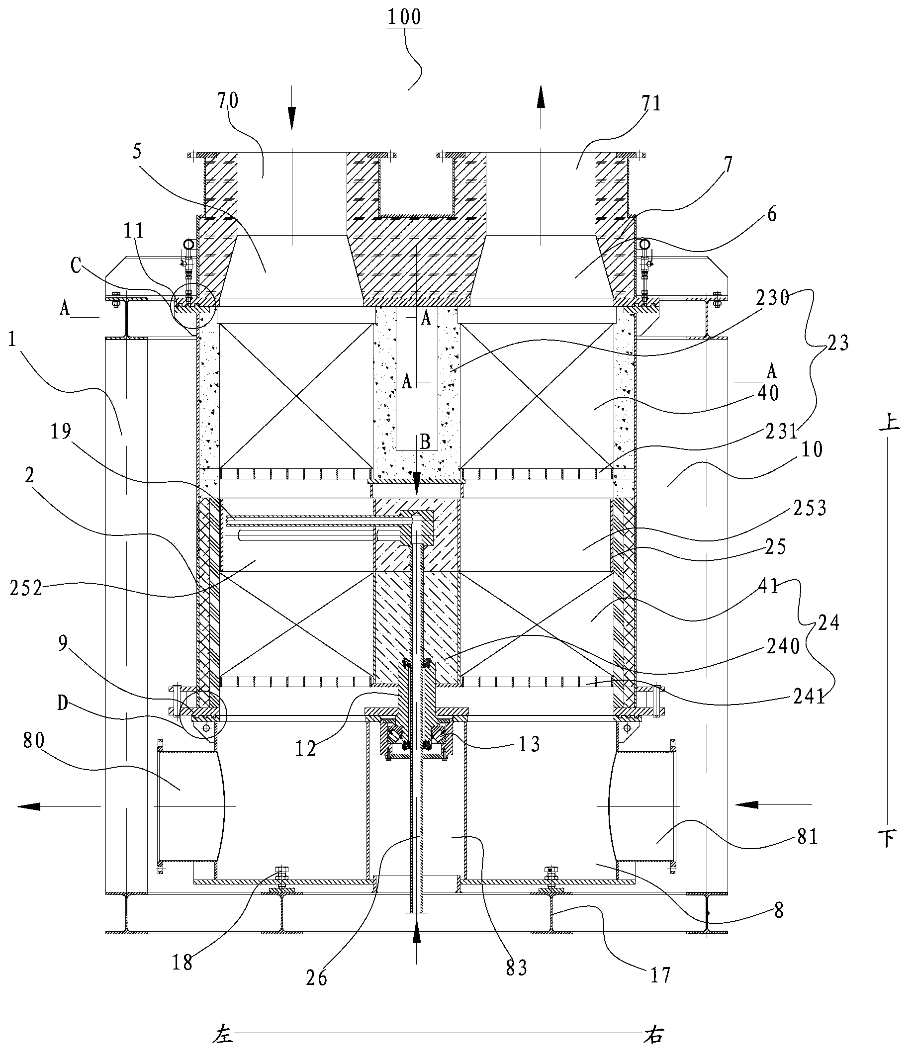
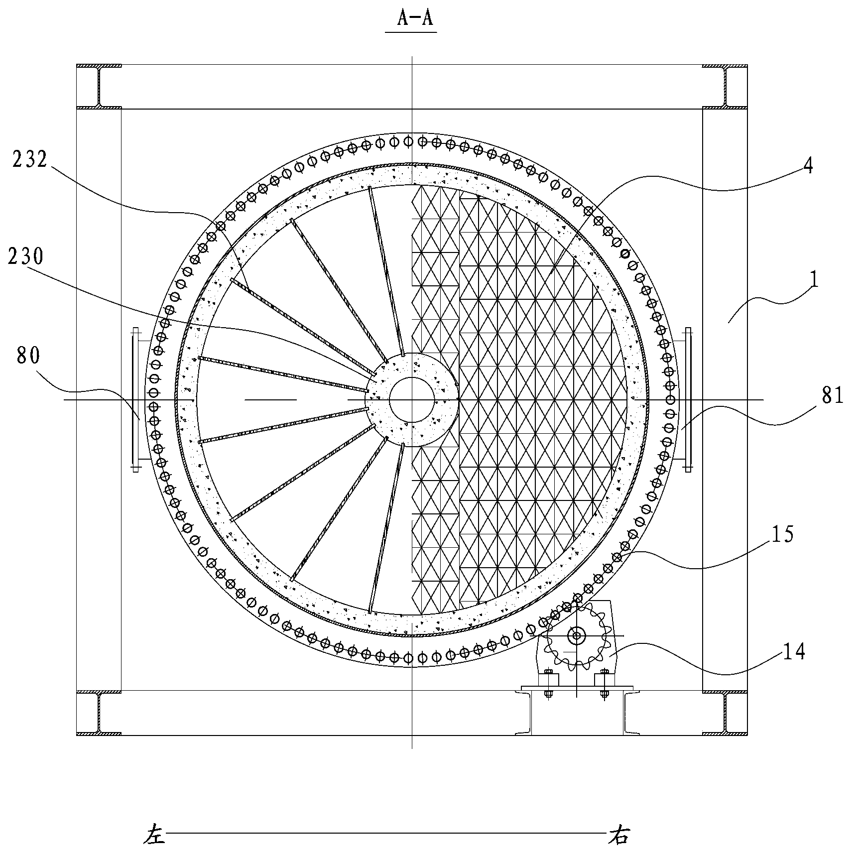
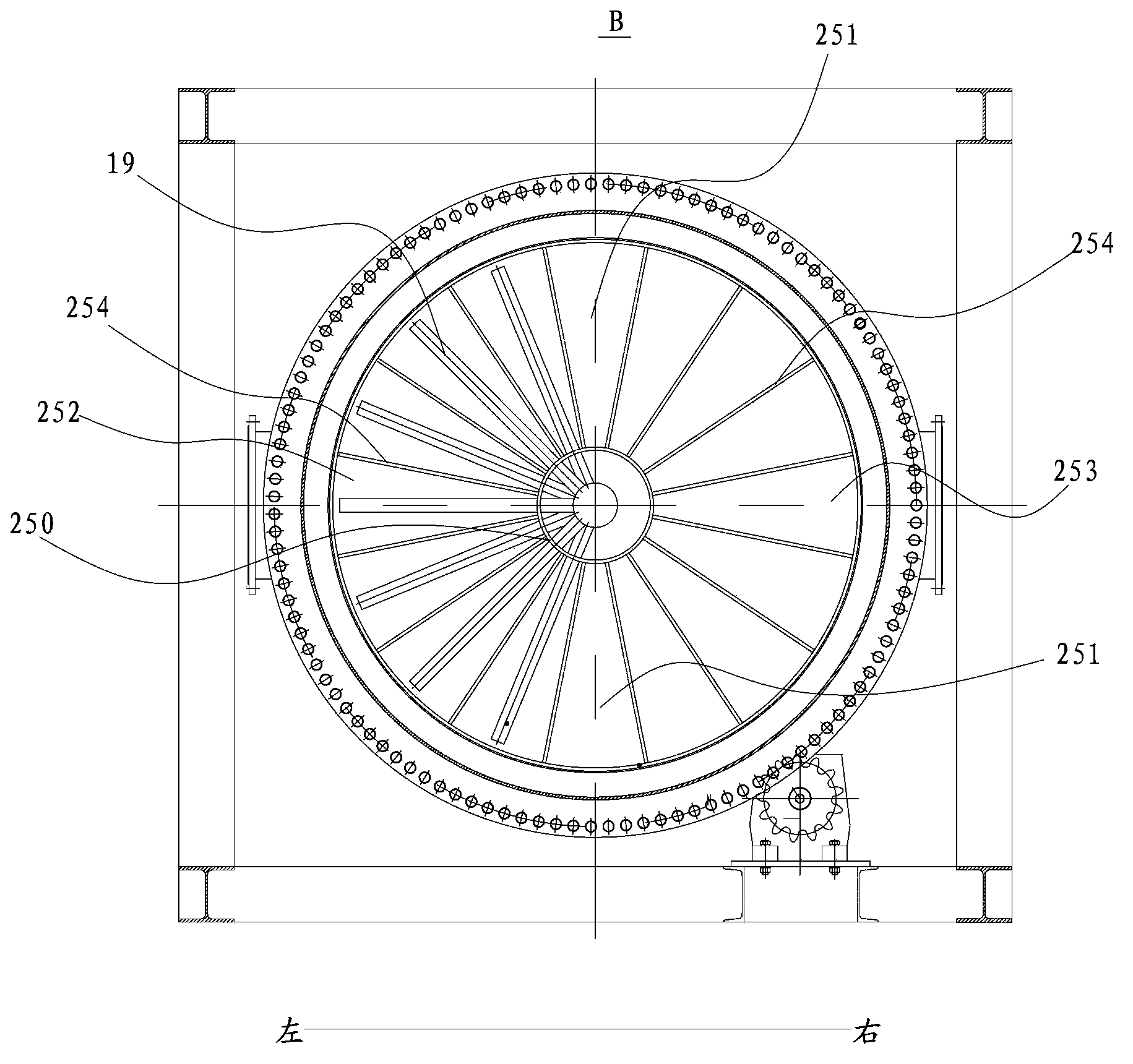
The invention discloses a catalytic purification and heat exchange system. The catalytic purification and heat exchange system comprises a shell, a heat exchanger main body, a separation element, a heat carrier, a flue gas channel and an air channel, wherein a cavity is defined by the shell; the heat exchanger main body is arranged in the cavity and can rotate around the central axis of the heat exchanger main body; the separation element is arranged in the heat exchanger main body along the central axis, and the heat exchanger main body is separated into a first containing part and a second containing part, which are opposite to each other; the heat carrier contains catalysts which are contained in the first containing part and the second containing part, respectively; the flue gas channel is communicated with one of the first containing part and the second containing part, and the air channel is communicated with the other one of the first containing part and the second containing part so as to enable air and the heat carrier contained in the containing parts to exchange heat. According to the catalytic purification and heat exchange system provided by the invention, harmful gases can be removed through continuous catalysis, or waste heat can be recycled in the denitrification process.

Description

technical field [0001] The invention relates to the technical field of heat exchange, in particular to a catalytic purification and heat exchange system. Background technique [0002] In the existing process of denitrification or removal of other harmful gases, it needs to be carried out under a certain temperature. For example, in the prior art, the low-temperature flue gas is usually heated to a certain temperature before denitrification, or the hot flue gas is denitrified intermittently by using the reversing method. The problem caused by this is that a large part of energy is wasted in flue gas heating , and the denitrification effect is poor. Contents of the invention [0003] The present invention aims to solve at least one of the technical problems existing in the prior art. Therefore, an object of the present invention is to propose a catalytic purification and heat exchange system that can realize the reuse of waste heat in the process of continuous catalytic re...

Claims


Application Information

Patent Timeline
Patent Type & Authority Applications(China)
IPC IPC(8): B01D53/86B01D53/56F28D17/00
CPCF28D19/041F28D19/047
Inventor 吴道洪吴荣湘
Owner SHENWU TECH GRP CO LTD
Learn More