Direct Drive Primary Structures for Roller Mills

A direct-drive main and roller mill technology, applied in grain processing, etc., can solve the problems of reducing the rated output of the roller mill, the length of the power transmission chain, and the poor rigidity of the pendulum G, so as to reduce the transmission chain components and improve the milling efficiency. Effect of pressure, increased rigidity and smooth running

Active Publication Date: 2016-02-24
HENAN LIMING HEAVY IND SCI & TECH +1
View PDF7 Cites 0 Cited by
  • Summary
  • Abstract
  • Description
  • Claims
  • Application Information

AI Technical Summary

Problems solved by technology

The deficiencies in the above-mentioned prior art are: 1. Due to the limitation of the spatial position of the support bushing B and the power input shaft C, the maximum diameter of the roller H of the grinding roller assembly F is also limited, thereby reducing the rated capacity of the roller mill. Yield
2. The power input is from the power input shaft C, the hanger D, and the swing rod G, and finally output to the grinding roller assembly F, which makes the power transmission chain longer, resulting in poor rigidity of the swing rod G, and easily causes vibration during work

Method used


Image

  • Direct Drive Primary Structures for Roller Mills
  • Direct Drive Primary Structures for Roller Mills
  • Direct Drive Primary Structures for Roller Mills

Examples


Embodiment 1

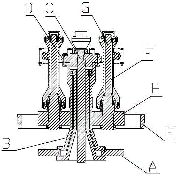
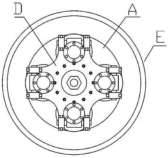
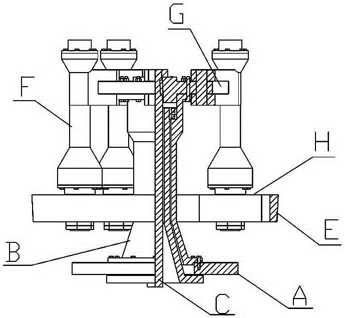
[0021] like Figure 3-1 , Figure 2-2 As shown, the direct-drive main structure for the roller mill of the present invention includes a blade base plate 1, a grinding ring 2 fixed on the base of the roll mill around the blade base plate 1, and the The grinding roller 3 rolling on the inner ring surface of the grinding ring 2 and the power input shaft 4 driven by the motor; the power input shaft 4 is vertically fixed on the middle part of the lower surface of the shovel seat plate 1 or connected with the shovel through a transmission part The lower plate surface of the base plate 1 is connected by transmission; the grinding roller 3 is arranged on the upper plate surface of the blade base plate 1 through a transmission mechanism; The pin shaft 5 is hinged to the horizontal swing rod 6 , and the roller shaft 7 of the grinding roller 3 is fixed vertically upward on the other end of the horizontal swing rod 6 .

Embodiment 2

[0023] like Pic 4-1 , Figure 4-2 As shown, the direct-drive main structure for the roller mill of the present invention includes a blade base plate 1, a grinding ring 2 fixed on the base of the roll mill around the blade base plate 1, and the The two grinding rollers 3 rolling on the inner ring surface of the grinding ring 2 and the power input shaft 4 driven by the motor; the power input shaft 4 is vertically fixed on the middle part of the lower plate surface of the shovel holder plate 1 or connected with the The lower plate surface of the shovel seat plate 1 is connected by transmission; the two grinding rollers 3 are respectively arranged on the upper plate surface of the shovel knife seat plate 1 through a transmission mechanism; the transmission mechanism is vertically fixed on the upper plate surface of the shovel knife seat plate 1 The support bar 8 and the horizontal hanger 9 fixed on its top; the two grinding rollers 3 are arranged vertically downward symmetricall...

Embodiment 3

[0025] like Figure 5-1 , Figure 5-2 As shown, the direct-drive main structure for the roller mill of the present invention includes a blade base plate 1, a grinding ring 2 fixed on the base of the roll mill around the blade base plate 1, and the The grinding roller 3 rolling on the inner ring surface of the grinding ring 2 and the power input shaft 4 driven by the electric motor; The inner guide rail 12, the roller shaft 7 of the grinding roller 3 is fixed vertically upward on the end of the guide rail 12 extending out of the horizontal chute 11.


PUM


Abstract

The invention discloses a direct-drive main structure used for a roller mill. The direct-drive main structure comprises a tool apron seat disc, a grinding ring, a grinding roller and a power input shaft, wherein the grinding ring is fixedly arranged on a machine base of the roller mill around the tool apron seat disc, the grinding roller is in rolling fit with the inner ring surface of the grinding ring, the power input shaft is vertically and fixedly arranged at the middle part of the lower disc surface of the tool apron seat disc or is in transmission connection with the lower disc surface of the tool apron seat disc through a transmission part, and the grinding roller is arranged on the upper disc surface of the tool apron seat disc through a transmission mechanism. The direct-drive main structure has the advantages that the power input shaft is vertically and fixedly arranged at the middle part of the lower disc surface of the tool apron seat disc or is in transmission connection with the lower disc surface of the tool apron seat disc through the transmission part, so that the space occupied by a supporting shaft sleeve B and a power input shaft C in the prior art is saved, and accordingly, the effective volume of the roller mill is expanded under the same grinding ring diameter condition, in such a way, the diameter of the grinding roller is made larger and the height of the grinding roller is made greater, therefore the goal of improving the rolling compaction force, the rotational inertia and the rated output of the grinding roller is achieved, and the rigidity and the operation stability of a system are also improved.

Description

technical field [0001] The present invention relates to a main structure of a roller mill, in particular to a direct-drive main structure for a roller mill. Background technique [0002] At present, the main structure of the existing vertical roller mill is as follows Picture 1-1 , Figure 1-2 , Figure 2-1 , Figure 2-2 As shown, it includes the blade base plate A, the support sleeve B fixed vertically upward at the center of the blade base plate A, the power input shaft C that runs through the blade base plate A and the support sleeve B from bottom to top, and is horizontal The hanger D fixed on the top of the power input shaft C and the support bushing B, the grinding ring E fixed on the frame around the shovel plate A, and the grinding roller assembly F rolling with the inner ring surface of the grinding ring E are composed. The grinding roller assembly F is fixedly connected to the hanger D through the swing bar G, and there are two connection forms. Figure 1 shows ...

Claims


Application Information

Patent Timeline
Patent Type & Authority Patents(China)
IPC IPC(8): B02C15/08
Inventor 宁晋
Owner HENAN LIMING HEAVY IND SCI & TECH
Why Eureka
Try Eureka