Vertical mixing fermentation tank

A fermenter and stirring shaft technology, applied in the field of fermenter, can solve problems such as difficulty in stirring evenly and thoroughly, large mechanical structure, and large mechanical agitator resistance, and achieve the effects of reducing the probability of failure, simplifying the mechanical structure, and reducing the need

Inactive Publication Date: 2014-03-26
麦行
View PDF5 Cites 19 Cited by
  • Summary
  • Abstract
  • Description
  • Claims
  • Application Information

AI Technical Summary

Problems solved by technology

In this process, because the mixing system needs to stir and turn the whole tank of materials, the resistance of the mechanical stirrer is relatively large, and the driving power is relatively high, generally 2-4kw/m 3 , the driving motor needs a lot of power, and the reducer is huge and complicated, which is a huge burden for large solid fermentation tanks and is p

Method used


Image

  • Vertical mixing fermentation tank
  • Vertical mixing fermentation tank
  • Vertical mixing fermentation tank

Examples


Embodiment 1

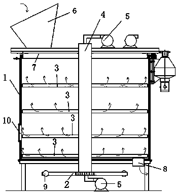
[0036] This embodiment provides a vertical stirring fermenter, which includes a tank body 1 and an upper cover, a feeding device 6, an air blowing device 5, an air exhausting device and a stirring and discharging device.

[0037] The bottom of the tank body 1 is flat, with a discharge port, a door switch, a discharge device, and a wind net. The tank body 1 can be a double-layer structure, and the middle of the double-layer is filled with heat-insulating material, and there are multiple air outlets on the inner surface to supply oxygen for the fermented product in the fermenter. The tank body 1 is provided with a manhole 10 that allows people to pass through, which is convenient for repair.

[0038] The feeding device 6 includes a receiving hopper located on the upper cover 7, and a gate is installed under the receiving hopper, so that the sealing of the tank body 1 can be effectively maintained.

[0039] The blower device 5 and the draft device can be installed in a suitable ...

Embodiment 2

[0054] Example 2 Research on energy consumption of motors.

[0055] According to the structure of Example 1, the present invention has designed fermentors with volumes of 3, 5, 10, 20, 40 and 60 cubic meters respectively, and adopted a conventional solid fermentor of 10 cubic meters for comparison, and packed Waste, measure the required power of each fermentation tank, the results are shown in Table 1

[0056] Table 1 Power required by each fermenter

[0057] Fermenter type required power 10 cubic meters of conventional solid fermenter The required power of the stirring motor is 37 kW 3 cubic meters of fermenters designed according to embodiment 1 The power provided to the hydraulic cylinder is 0.75 kW 5 cubic meters of fermenters designed according to embodiment 1 The power provided to the hydraulic cylinder is 0.75 kW 10 cubic meters of fermentation tank designed according to embodiment 1 The power provided to the hydraulic cylind...


PUM


Abstract

The invention provides a vertical mixing fermentation tank which comprises an upper cover, a tank body, a mixing discharging device, a feeding device, a blower device and a ventilation device, wherein the mixing discharging device comprises a hollow mixing shaft, a plurality of mixing blades connected onto the mixing shaft and a ratchet mechanism at the bottom of the tank body; the mixing blades attached to the bottom of the tank body have functions of discharge blades; the mixing blades are hollow, and air outlets are formed in the mixing blades; and the hollow mixing shaft is connected with the ratchet mechanism at the bottom of the tank body, and the ratchet mechanism is pushed by a push-pull mechanism. The power required by a mixing motor of a large fermentation tank is remarkably reduced by changing mixing and transmission manners, the mechanical structure is simplified while energy consumption is reduced, the probability of failures of a machine is reduced, and the vertical mixing fermentation tank is suitable for omnibearing uniform mixing and easy discharging of the large fermentation tank.

Description

technical field [0001] The present invention relates to a fermenter, more particularly, to a large fermenter. Background technique [0002] Fermentation tanks generally refer to devices used in industry for microbial fermentation. From the perspective of the fermentation content, there are currently two types of fermenters, one is a liquid fermenter and the other is a solid fermenter. Both of them need to use a motor to achieve stirring. Depending on the viscosity of the liquid and the size of the fermenter, the power of the motor required for the stirring of the liquid fermenter ranges from 10 to 100 kilowatts; there is no mature technology for the stirring of the solid fermenter. At present, there are mainly small fermenters and horizontal fermenters. For medium-sized fermentation tanks with type stirring, the driving force of the mixing system is mainly realized by the motor driving the reducer to generate huge torque. Generally speaking, for solid fermentation tanks of ...

Claims


Application Information

Patent Timeline
IPC IPC(8): B09B3/00
Inventor 麦行其他发明人请求不公开姓名
Owner 麦行
Why Eureka
Try Eureka