Split type hot continuous rolling cooling water retaining structure

A water-retaining structure and cooling water technology, applied in the direction of roll, metal rolling, metal rolling, etc., can solve the problems of deformation of the cooling water header frame body of the roll, unable to recover quickly, etc., to improve the rolling operation rate and simple structure. , to eliminate the effect of local deformation

Active Publication Date: 2014-03-26
XINYU IRON & STEEL CO LTD
View PDF6 Cites 3 Cited by
  • Summary
  • Abstract
  • Description
  • Claims
  • Application Information

AI Technical Summary

Problems solved by technology

[0003] In order to solve the problem that the local deformation of the existing roll cooling water header body cannot be recovered quickly, the present invention provides a split water retaining plate structure, which not only It can prevent the cooling water on the surface of the roll from entering the rolling deformation zone, and can easily and quickly replace the deformed part, eliminating the influence of the local deformation of the cooling water header body of the roll

Method used


Image

  • Split type hot continuous rolling cooling water retaining structure
  • Split type hot continuous rolling cooling water retaining structure
  • Split type hot continuous rolling cooling water retaining structure

Examples


Embodiment 1

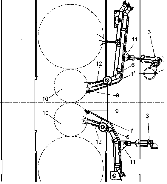
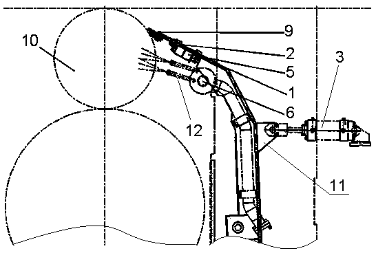
[0021] Example 1: The present invention is a split cooling water retaining structure for hot continuous rolling, which is used in pairs and installed directly opposite to the rolling mill to cool the upper and lower work rolls 10 . figure 2 Shown is a schematic view of the present invention installed on the lower work roll 10 in use, combined with image 3 , including: the first mounting frame body 1 and the second mounting frame body 2 are both made of 20mm-25mm steel plates, the first mounting frame body 1 is a curved arc panel, and the concave surface is equipped with a roll cooling water header 6, and the convex surface is set There are lugs 11, and the lugs 11 are connected with the cylinder piston rod 3; the second installation frame body 2 is a flat plate, and its front end is equipped with a water cutting plate 9, which is fixed with bolts, and the water cutting plate 9 is closely attached to the working surface by the pressure of the cylinder. On the surface of the...

Embodiment 2

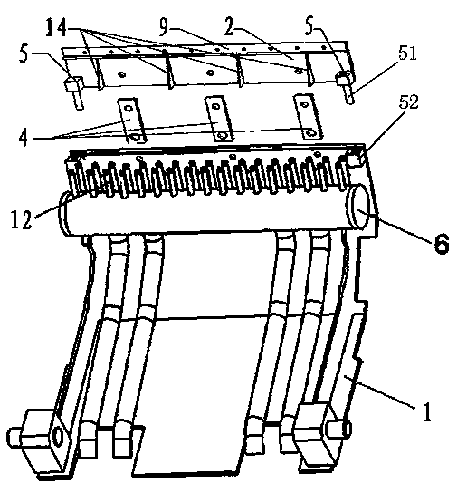
[0022] Example 2: Such as Figure 4~7 As shown, in order to facilitate disassembly and assembly, the present invention provides a schematic front view of another fixing method.

[0023] Such as Figure 7 As shown, one end of the connector 4 is provided with an opening slot 41 and both sides are provided with grooves 43, and the middle of the other end is provided with a "one"-shaped groove 42, which is convenient to install according to the first installation frame body 1 and the second installation frame body 2. Adjust the fixed position of the bolt 8 through the mounting holes provided on both sides of the corresponding connection side. Such as Figure 4~6 As shown, the two ends of the locking plate 7 are bent in a “П” shape, and the center is provided with a bolt 8 connecting hole, and the curved end of the locking plate 7 is stuck in the groove 41 of the connecting piece 4, and then the locking plate 7 is locked by the bolt 8. Connect with the second mounting frame bo...


PUM


Abstract

The invention discloses a split type hot continuous rolling cooling water retaining structure which comprises a first mounting frame body, a second mounting frame body and a connecting piece. A roller cooling water collecting pipe is mounted on the concave face of the first mounting frame body, a jet nozzle is mounted opposite to the direction of a working roller in the roller cooling water collecting pipe, a lug piece is arranged on the convex face of the first mounting frame body, and the lug piece is connected with a piston rod of an air cylinder. A water cutting board is mounted at the front end of the second mounting frame body. The front end of the first mounting frame body and the rear end of the second mounting frame body are in L-shaped step face lap joint corresponding to connecting edges, and are fixed through the connecting piece to be integrally connected. According to the split type hot continuous rolling cooling water retaining structure, the front portion of a frame body of the rolling cooling water collecting pipe is designed to be of a split type structure, cooling water on the surface of a roller can be stopped from entering a rolling deformation area, the front portion which can be deformed easily can be replaced quickly and conveniently, the time for maintaining and replacing is shortened, and steel rolling operation efficiency is improved.

Description

technical field [0001] The invention relates to a cooling water retaining device for hot continuous rolling, which is used to prevent the cooling water of rolls of a hot continuous rolling mill from entering the rolling deformation zone, in particular to a split cooling water retaining structure for hot continuous rolling. Background technique [0002] Cooling water is needed to cool the rolls during hot rolling mill rolling, in order to prevent the rolls from being damaged by the heat transfer of high-temperature rolled pieces. At present, known roll cooling devices such as figure 1 , is formed by integral assembly of water cutting plate 9, roll cooling water header 6, roll cooling water header frame body 1' and the cylinder on the frame body. The water cutting plate 9 is made of high-temperature-resistant phenolic resin material, and is installed at the front end of the roll cooling water header body 1'. The surface is in close contact, and the cooling water sprayed from...

Claims


Application Information

Patent Timeline
Patent Type & Authority Applications(China)
IPC IPC(8): B21B27/10
Inventor 唐彬桂王晓东宋晓斌胡建敏陈奋张立民邹苏华杨帆
Owner XINYU IRON & STEEL CO LTD
Why Eureka
Try Eureka