
High-accuracy gear milling machine for gear and rack

A high-precision, gear milling machine technology, applied in the direction of belt/chain/gear, gear teeth, mechanical equipment, etc., can solve the problems of weak rigidity, long main transmission chain, inability to process racks, etc., to improve rigidity and expand processing. range effect

Active Publication Date: 2014-03-26
CHONGQING MACHINE TOOL GROUP
View PDF8 Cites 12 Cited by
  • Summary
  • Abstract
  • Description
  • Claims
  • Application Information

AI Technical Summary

Problems solved by technology

When processing larger diameter inner ring gears, the gear shaping method was commonly used in the past, the efficiency of gear shaping is lower, and racks cannot be processed; in addition to gear shaping, some manufacturers also use old-fashioned gear milling machines, old-fashioned gear milling machines The vertical and horizontal layout is adopted, and the layout is similar to that of the vertical lathe. Although the efficiency of this old-fashioned gear shaping machine is higher than that of the gear shaping machine, and it can process racks, but due to the long main drive chain and weak rigidity, milling out Tooth accuracy is not very ideal
At present, the special machine tools for processing racks can only process racks, but not gears.

Method used


Image

  • High-accuracy gear milling machine for gear and rack
  • High-accuracy gear milling machine for gear and rack
  • High-accuracy gear milling machine for gear and rack

Examples


Embodiment Construction

[0026] Hereinafter, preferred embodiments of the present invention will be described in detail with reference to the accompanying drawings. It should be understood that the preferred embodiments are only for illustrating the present invention, but not for limiting the protection scope of the present invention.

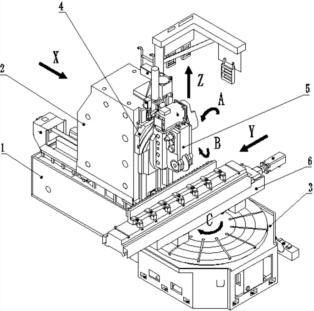
[0027] As shown in the figure, a high-precision gear and rack milling machine includes a bed 1, a large column 2, a workbench 3, a slide plate 4, a milling tool holder 5 and a rack feed unit 6; the large The column is installed on the bed, and the bed is provided with an X-axis driving mechanism that drives the radial feed of the large column; the slide plate is installed on the large column, and the large column is provided with a Z-axis that drives the axial feed of the slide plate Drive mechanism; the milling tool holder is installed on a slide plate, and the slide plate is provided with an A-axis driving mechanism that drives the rotation of the milling tool holder...


PUM


Abstract

The invention discloses a high-accuracy gear milling machine for a gear and a rack, which comprises a bed, a big upright, a working table, a sliding plate, a gear milling too rest and a rack feeding unit. The big upright is arranged on the bed; the bed is provided with an X-axis driving mechanism for driving the big upright to carry out radial feeding; the sliding plate is arranged on the big upright; the big upright is provided with a Z-axis driving mechanism for driving the sliding plate to carry out axial feeding; the gear milling tool rest is arranged on the sliding plate; the gear milling tool rest is also provided with a B-axis driving mechanism for driving a gear milling tool spindle to rotate; the rack feeding unit is arranged on the working table in a detachable manner; the rack feeding unit is provided with a Y-axis driving mechanism for driving the rack to be tangentially fed; and the working table is also provided with a C-axis driving mechanism for driving the working table to rotate. The gear milling machine disclosed by the invention not only can be used for machining internal and external gears, but also can be used for machining the rack; the machining range of the machine tool is expanded; and meanwhile, rigidity, stability, gear milling efficiency and machining accuracy of the machine tool are improved.

Description

technical field [0001] The invention belongs to the field of gear milling machine tools, in particular to a high-precision gear and rack milling machine. Background technique [0002] At present, the processing of gear parts mainly includes rolling, shaving, inserting, and grinding. However, the efficiency of hobbing machines is low when rolling large-diameter, large-modulus external gears. When processing larger diameter inner ring gears, the gear shaping method was commonly used in the past, the efficiency of gear shaping is lower, and racks cannot be processed; in addition to gear shaping, some manufacturers also use old-fashioned gear milling machines, old-fashioned gear milling machines The vertical and horizontal layout is adopted, and the layout is similar to that of the vertical lathe. Although the efficiency of this old-fashioned gear shaping machine is higher than that of the gear shaping machine, and it can process racks, but due to the long main drive chain and w...

Claims


Application Information

Patent Timeline
Patent Type & Authority Applications(China)
IPC IPC(8): B23F5/20B23Q5/28B23Q5/10
Inventor 李樟李先广廖承渝李明伟
Owner CHONGQING MACHINE TOOL GROUP
Learn More