Center frame of square tube laser cutting machine

A technology of center frame and cutting machine, which is applied to laser welding equipment, tubular objects, manufacturing tools, etc. It can solve the problems of square tubular workpieces without clear and effective solutions, low processing accuracy, and limited processing range.

Active Publication Date: 2014-03-26
WUHAN FARLEYLASERLAB CUTTING SYST ENG +1
View PDF6 Cites 22 Cited by
  • Summary
  • Abstract
  • Description
  • Claims
  • Application Information

AI Technical Summary

Problems solved by technology

The traditional center frame generally adopts the principle of three-point fixed circle to clamp and support the shaft-shaped workpiece, but it can't do anything for the square tubular workpiece.
There has been no clear and effective solution for the clamping of square tubular workpieces, resulting in the processing range being limited to shaft workpieces
Moreover, in the processing process, the traditional center frame structure and the workpiece have no relative axial movement, so that it is impossible to cooperate with the laser head or the mechanical cutter head for high-precision, high-accuracy, and high-stability axial feed processing
In addition, it is difficult for the general steady frame to guarantee accurate synchronous movement (that is, the same direction and the same speed) with the spindle box, resulting in low machining accuracy and low machining efficiency.

Method used


Image

  • Center frame of square tube laser cutting machine
  • Center frame of square tube laser cutting machine

Examples


Embodiment Construction

[0017] In order to make the object, technical solution and advantages of the present invention clearer, the present invention will be further described in detail below in conjunction with the accompanying drawings and embodiments. It should be understood that the specific embodiments described here are only used to explain the present invention, not to limit the present invention.

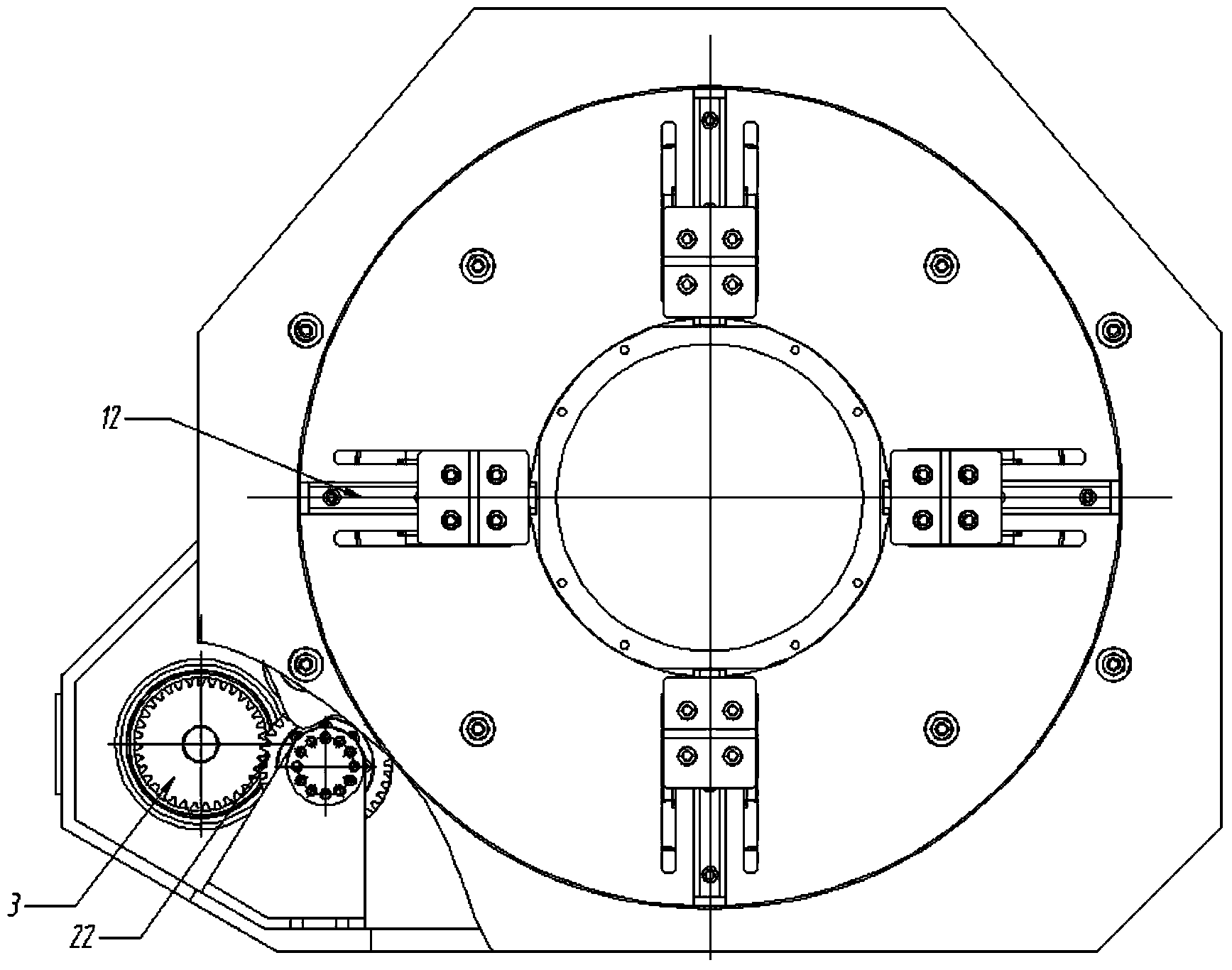
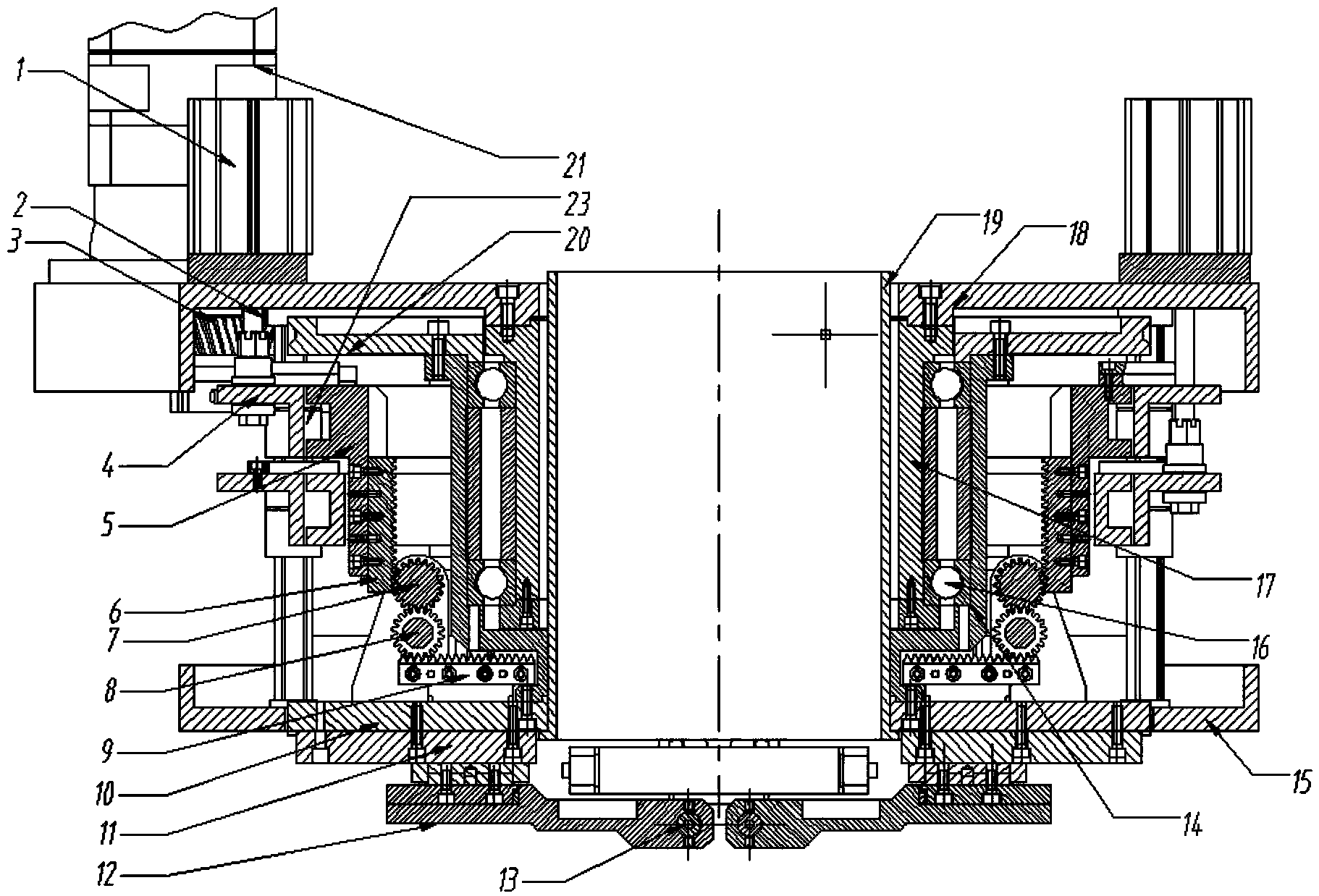
[0018] Such as Figure 1-2 As shown, the center frame of the present invention includes four main mechanisms: a synchronous clamping support mechanism, a synchronous rotation control mechanism, a hollow center frame structure and a pipe axial movement mechanism. Among them, the synchronous clamping support mechanism is: four claws 12 with rollers 13 evenly distributed on the front circular cover 11; four cylinders 1 evenly distributed on the rear circular cover 18, each cylinder controls One claw, and every two pairs, install a pair on the top and bottom of the center frame, respectively control t...


PUM


Abstract

The invention discloses a center frame of a square tube laser cutting machine. The center frame used for supporting and clamping square tube workpieces and synchronously rotating with a spindle motor mainly comprises a synchronous clamping supporting mechanism, a synchronous rotating control mechanism, a hollow center frame structure, and a tube axial movement mechanism. The four mechanisms operate in coordination to clamp and support square tubes, under high precision, high accuracy and high stability, and axially feed the square tubes for laser machining. The workpieces can be clamped and supported accurately in sync through the synchronous clamping supporting mechanism; a rotating motor can drive a claw and a clamped workpiece to rotate in sync through the synchronous rotating control mechanism. The hollow center frame structure can coordinate with the tube axial movement mechanism to axially move the square tubes for machining. The center frame allows the square tube workpieces to be clamped and supported accurately, can rotate in sync with the spindle motor, and allows for axial movement for machining; accordingly, machining range is widened, and machining efficiency and machining precision are improved.

Description

technical field [0001] The invention belongs to the technical field of laser square tube cutting machine equipment, and relates to a center frame for a laser square tube cutting machine, in particular to a center frame structure for processing and clamping some square tubes. Background technique [0002] In mechanical processing and laser processing, there will be a step of clamping and fixing the workpiece, and the steady rest is an auxiliary device for radially supporting the rotating workpiece during processing. The traditional center frame generally adopts the principle of three-point fixed circle to clamp and support the shaft-shaped workpiece, but it can't do anything for the square tubular workpiece. There has been no clear and effective solution for the clamping of square tubular workpieces, resulting in the limitation of the processing range to shaft workpieces. Moreover, in the process of processing, the traditional center frame structure and the workpiece do not ...

Claims


Application Information

Patent Timeline
Patent Type & Authority Applications(China)
IPC IPC(8): B23K26/70
CPCB23K26/0823B23K26/083B23K26/38B23K2101/06
Inventor 邵新宇李斌郭平华段正澄黄禹王征张雅飞王玉姣范大鹏张臻李建
Owner WUHAN FARLEYLASERLAB CUTTING SYST ENG
Why Eureka
Try Eureka