Demoulding structure for plastic helical gear injection molding

An injection molding, helical gear technology, applied in the direction of gears, other household appliances, household appliances, etc., can solve the problems of helical gear helical shape deformation, gear cavity cracks, longer injection molding cycle, etc., and shorten the molding cycle. , the mold structure is compact, the effect of ensuring the strength

Inactive Publication Date: 2014-03-26
SHENZHEN HISYM IND
View PDF4 Cites 20 Cited by
  • Summary
  • Abstract
  • Description
  • Claims
  • Application Information

AI Technical Summary

Problems solved by technology

There will be many problems in the actual implementation of this scheme: the above-mentioned structure cannot be provided with a cooling water channel on the gear cavity due to the rotational movement of the gear cavity, and the heat generated by the molten plastic injected by the injection molding machine cannot be quickly transferred through the gear cavity Out, resulting in longer injection molding cycle, high efficiency and low cost, and also lead to uneven shrinkage and deformation of the helical gear helical shape, which affects the precision of the product. The gear cavity is easy to burst, and the heat generated by the plastic during the injection molding process will be transmitted to the bearing through the gear cavity, making the internal structure of the bearing not slide smoothly. Characteristic deformation; for plastic helical gear molds with tooth position requirements, most of them currently adopt a structure similar to the Chinese patent No. "201110381777.3" published on June 5, 2013, "Resetting structure of helical gear mold and helical gear mold" , that is, the reset is completed by inserting the reset ejector pin fixed in the fixed mold cavity into the positioning hole of the movable gear cavity placed in the movable mold part. This structure needs to set a chute on the gear cavity to match the reset ejector head. In the specific implementation process, inclined slots and holes should be set on the gear cavity, the strength of the gear cavity will become weaker, and the gear cavity will easily be scrapped due to cracks at the positions of the inclined slots and holes. In the long-term production process, the reset lever is forced Toggle the gear cavity into the positioning hole, the positioning hole will become larger after long-term friction, so the reset accuracy of the gear cavity cannot be guaranteed

Method used


Image

  • Demoulding structure for plastic helical gear injection molding
  • Demoulding structure for plastic helical gear injection molding
  • Demoulding structure for plastic helical gear injection molding

Examples


Embodiment Construction

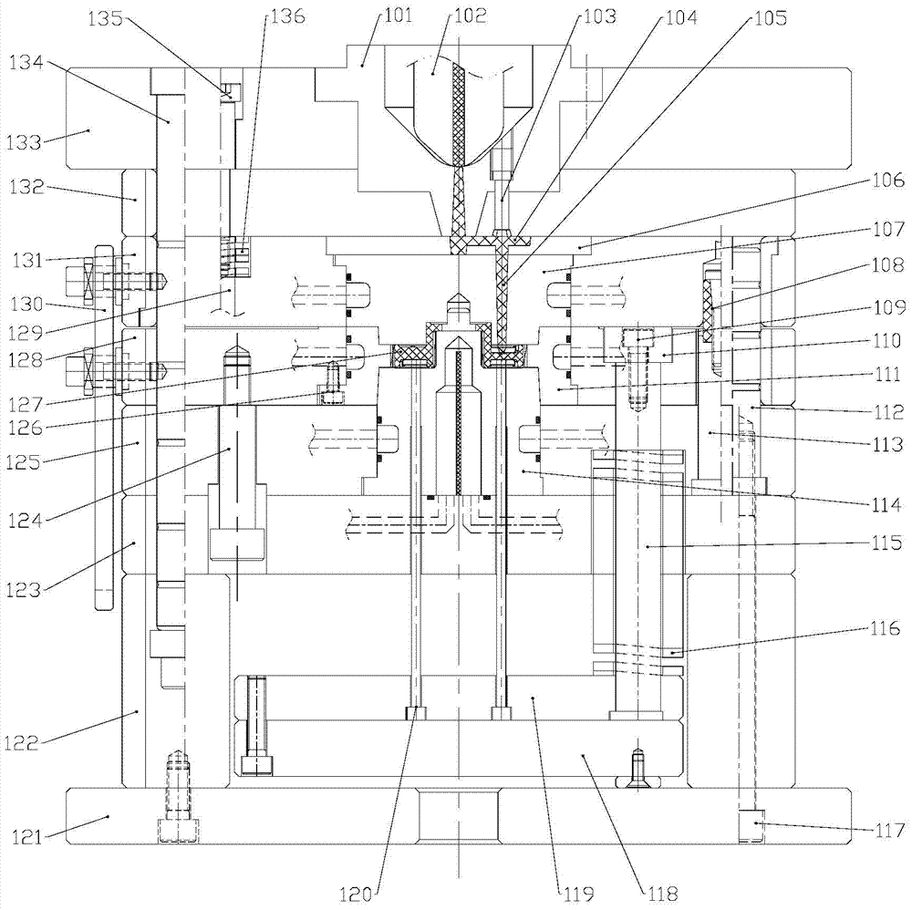
[0016] The present invention will be further elaborated below in conjunction with the accompanying drawings: the plastic helical gear mold includes a fixed mold part and a movable mold part.

[0017] like figure 1 As shown, the top plate 133 of the fixed mold part, the stripper plate 132 and the fixed mold cavity plate 131 are fixedly connected by the guide post 134 fixed on the top plate. The stripping plate 132 and the fixed mold cavity plate 131 can move under the guidance of the guide column 134, and the moving distance is limited by the stop screw 135 and the screw pull rod 129 arranged on the fixed mold part. Closed on the spring 136 on the screw pull rod 129 and the nylon rubber plug 108 control that is located on the fixed mold cavity plate 131, the spring 136 is contained between the stripping plate 132 and the fixed mold cavity plate 131 and is sleeved on the screw pull rod 129. The fixed mold cavity 107 is arranged on the fixed mold cavity plate 131 and is fixed on...


PUM


Abstract

The invention relates to the field of mould making, in particular to a demoulding structure for plastic helical gear injection molding. The plastic helical gear mould comprises a fixing mould part, a moving mould part, and a demoulding component comprising a pulling plate fixed on a fixing mould cavity plate and a gear cavity plate, and an ejection structure arranged on the moving mould part, wherein a fixing mould cavity positioned in the fixing mould cavity plate, a gear cavity positioned in the gear cavity plate, and a moving mould cavity in the moving cavity plate mutually form step shapes, and sequentially and tightly connected in a sleeving manner to form a helical gear cavity. During the demoulding process, under the effect of the demoulding component, the injection molded plastic helical gear rotationally moves forwards in a spiral manner along the inner surface of the gear cavity to realize mold stripping, so that the finished plastic helical gear is obtained. The structure has the advantages that the mould is simple in structure, high in product accuracy and stable in production, and overcomes difficulties of easiness in deformation of the spiral plastic helical gear during the injection process, gear ring cooling, gear ring resetting performed to satisfy the requirements for gear position.

Description

technical field [0001] The invention relates to the field of plastic helical gear mold manufacturing, in particular to a plastic helical gear injection molding demoulding structure. Background technique [0002] Plastic helical gears are widely used in modern industries. Compared with metal helical gears, they have the advantages of light weight, low running noise, and good self-lubrication. Plastic helical gears are mainly molded by injection molding, which has the characteristics of high efficiency and low cost. [0003] At present, most of the plastic helical gear injection molds adopt this kind of technical scheme that the gear cavity is driven by the straight helical gear product to make a rotary motion. Similar to the Chinese patent published on May 29, 2013, the patent number is "201310075397.6", " A "spiral demoulding device" structure for helical gear injection molds, which uses a device consisting of a rotating cavity, a moving mold carrier plate, a pressure plate...

Claims


Application Information

Patent Timeline
Patent Type & Authority Applications(China)
IPC IPC(8): B29C45/33B29C45/40
CPCB29C45/33B29C45/4435B29L2015/003
Inventor 张海臣周庆胜
Owner SHENZHEN HISYM IND
Why Eureka
Try Eureka