Trimming mechanism of plastic oil tank and method of trimming oil tank

A technology for plastic fuel tanks and fuel tanks, which is applied in the field of fuel tank trimming and plastic fuel tank trimming mechanisms, which can solve the problems of large total weight, inability to increase speed, and affect the efficiency of production lines, etc., and achieve the effect of small load and faster moving speed

Active Publication Date: 2014-03-26
YAPP AUTOMOTIVE PARTS
View PDF5 Cites 6 Cited by
  • Summary
  • Abstract
  • Description
  • Claims
  • Application Information

AI Technical Summary

Problems solved by technology

[0005] The plastic fuel tank blow molding production line produces a semi-finished fuel tank in about 93 seconds, and then the large robot completes the trimming operation. Before trimming, the semi-finished fuel tank must be grabbed and marked with a barcode. It takes more than 100 seconds to take, paste the barcode, trim and weigh the work, so the semi-finished fuel tank on the production line will be in a waiting state for a period of time, which affects the overall efficiency of the production line
Among them, the trimming action takes 70 seconds. Due to the large total weight of the fuel tank grabbing mechanism installed on the big robot and the semi-finished product of the fuel tank, the load of the large robot is high, and the speed cannot be increased when the semi-finished product of the fuel tank is clamped and rotated; High-load work will affect the life of the robot motor, and the after-sales maintenance cost is very expensive; and if the rotation speed of the plastic fuel tank is increased, the trimmed flash will easily wrap around and stick to the plastic fuel tank when the plastic fuel tank itself rotates, causing the product to be scrapped

Method used


Image

  • Trimming mechanism of plastic oil tank and method of trimming oil tank
  • Trimming mechanism of plastic oil tank and method of trimming oil tank
  • Trimming mechanism of plastic oil tank and method of trimming oil tank

Examples


Embodiment Construction

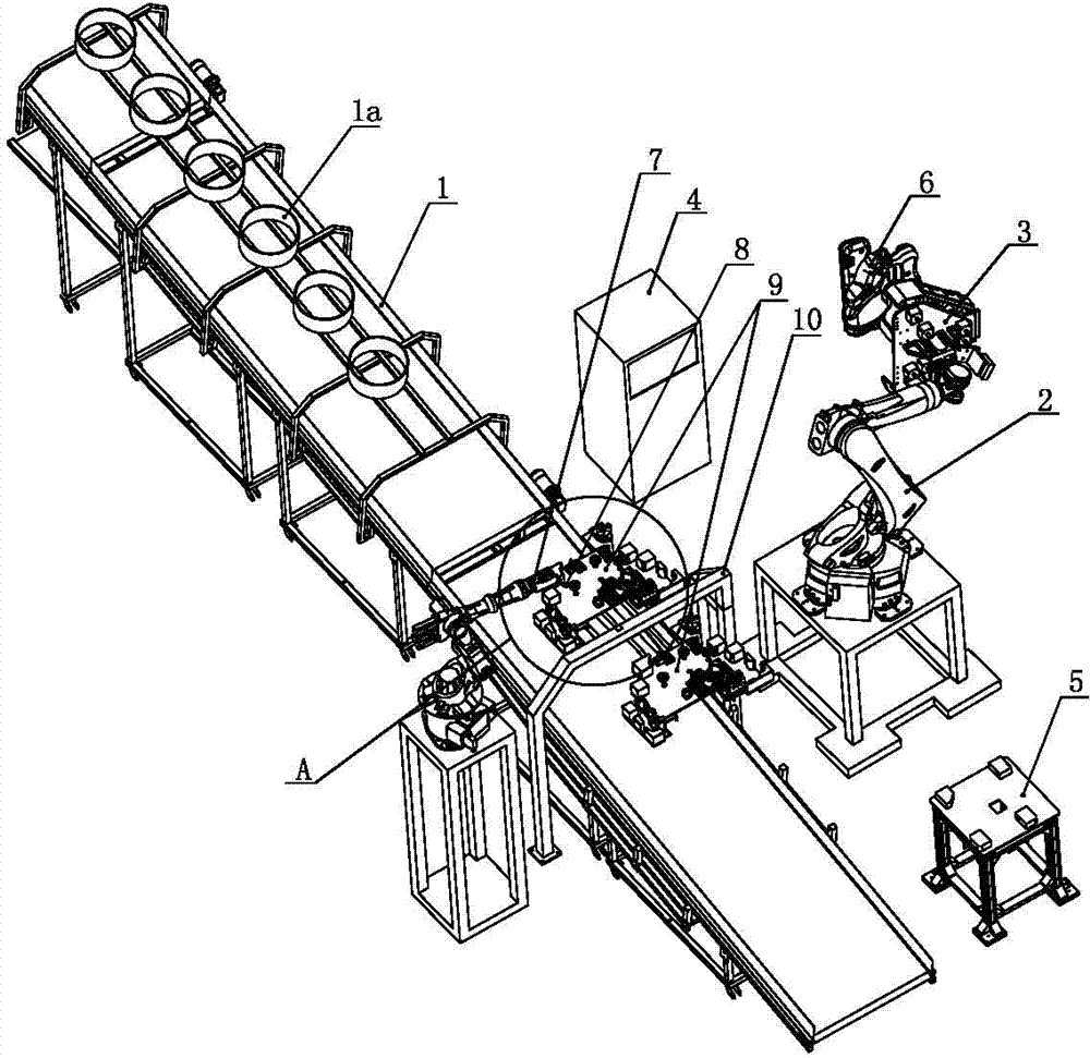
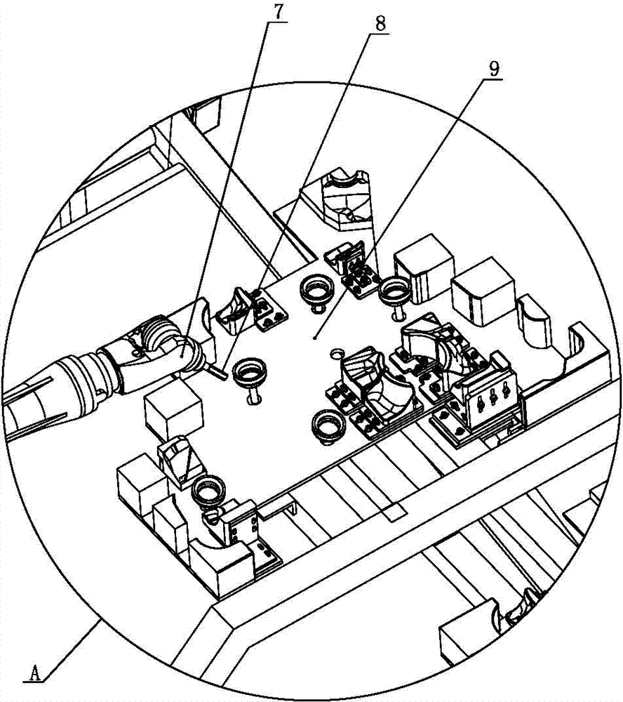
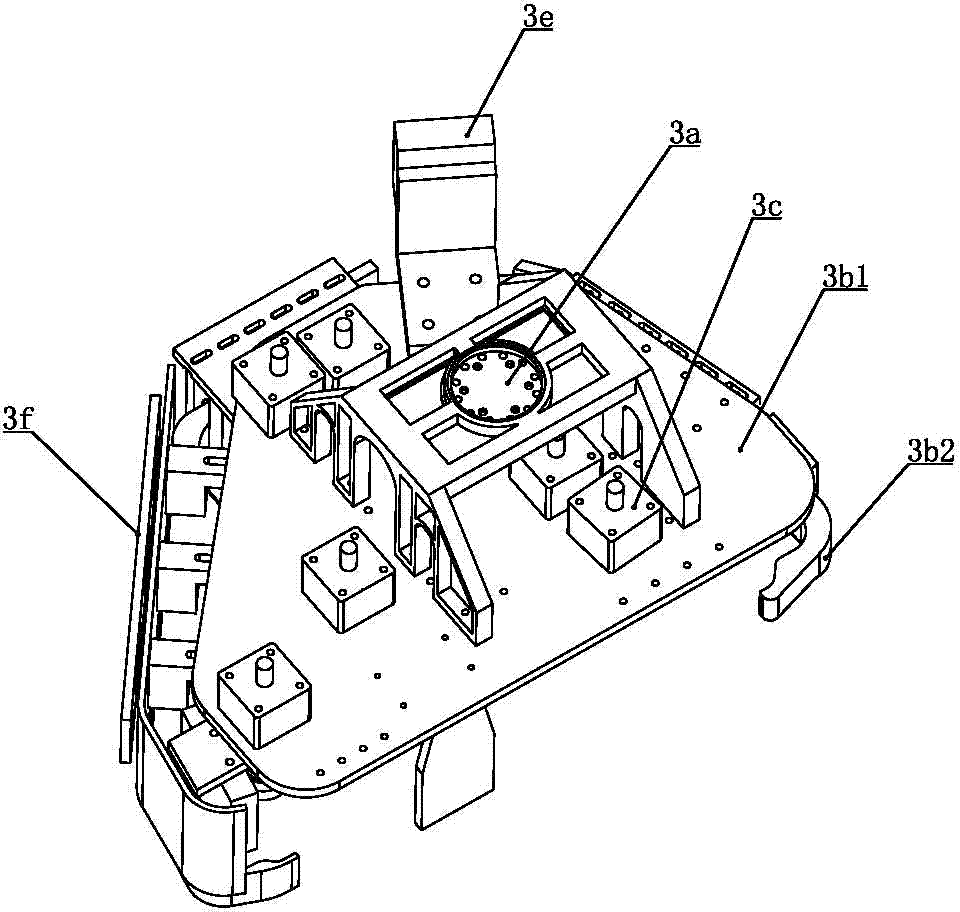
[0026] Such as Figure 1 to Figure 5 As shown, the plastic fuel tank trimming mechanism of the present invention includes a large robot 2, a bar code machine 4, a weighing platform 5 and a flash conveying line 1, and the large robot 2, a bar code machine 4 and a weighing platform 5 are all located at the flash conveying line 1 On the right side of the big robot 2, the end of the mechanical arm of the big robot 2 is equipped with a fuel tank grasping mechanism 3 that can grab a plastic fuel tank. Within the working stroke range of the arm, a small robot 7 is installed on the left side of the flash conveying line 1 opposite to the big robot 2, and the end of the mechanical arm of the small robot 7 is equipped with a tool that can cut off the flash of the plastic fuel tank clamping line. Trimming knife 8, two trimming platforms 9 with consistent shape and size are arranged side by side between the big robot and the small robot, and the two trimming platforms 9 are all fixed on th...


PUM


Abstract

The invention relates to a trimming mechanism of a plastic oil tank and a method of trimming the oil tank. The trimming mechanism comprises a big robot, a barcode printer, a weighing table and a trimming conveying line, wherein the big robot, the barcode printer and the weighing table are all located at the right side of the trimming conveying line, an oil tank grasping mechanism capable of grasping the plastic oil tank is arranged on the end of a mechanical arm of the big robot, the barcode printer and the weighing table are respectively arranged in a working travel range of the mechanical arm of the big robot, a small robot is arranged on a position, which is opposite to the big robot, at the left side of the trimming conveying line, a trimming knife capable of cutting trimmings of joint lines of the plastic oil tank is arranged on the end of a mechanical arm of the small robot, two trimming tables with the consistent shape and size are arranged between the big robot and the small robot in parallel, and the two trimming table are both fixed above the trimming conveying line. When one plastic oil tank is trimmed by the small robot, waiting, grasping, barcode pasting and weighing of another plastic oil tank can be completed by the big robot, and the trimming speed is quick, so that the production period is shortened, and the production efficiency is improved.

Description

technical field [0001] The invention relates to a manufacturing equipment of a plastic fuel tank, in particular to a plastic fuel tank trimming mechanism. The invention also relates to a method for trimming the edge of the fuel tank. Background technique [0002] The plastic fuel tank is formed by blow molding the parison in the cavity of the left and right half molds. The formed fuel tank has overflow around the parting line, forming a parting line flash; in addition, the welded nozzle on the side wall of the fuel tank Nozzle flash is also present. The flash needs to be removed by the trimming cutter mechanism. The traditional cutting method is to manually hold the plastic fuel tank and align the flash edge with the trimming tool for cutting. This trimming method has low production efficiency, high labor intensity and high skill requirements for operators; and the temperature of the plastic fuel tank just after forming is high, which is inconvenient to operate. The prod...

Claims


Application Information

Patent Timeline
Patent Type & Authority Applications(China)
IPC IPC(8): B29C49/42B29C49/72B29C37/02
Inventor 孙岩姜林徐松俊王震宇吴陆顺王昌儒葛迎辉赵贵勇
Owner YAPP AUTOMOTIVE PARTS
Why Eureka
Try Eureka