
Improved roller impressing device

An improved, roller technology, applied in the field of imprinting devices, can solve the problems of inability to achieve rapid production, too long imprinting time, and limited product size, such as the size of the master mold, to avoid the deformation of the transfer structure, improve the contact distance and effect of time

Inactive Publication Date: 2014-03-26
宁波市鄞州科启动漫工业技术有限公司
View PDF0 Cites 3 Cited by
  • Summary
  • Abstract
  • Description
  • Claims
  • Application Information

AI Technical Summary

Problems solved by technology

However, the product size of this embossing method is still limited by the size of the master mold, and the embossing time is too long, which cannot achieve the goal of rapid production

Method used


Image

  • Improved roller impressing device
  • Improved roller impressing device
  • Improved roller impressing device

Examples


Embodiment Construction

[0014] In conjunction with the accompanying drawings, the present invention will be described in further detail.

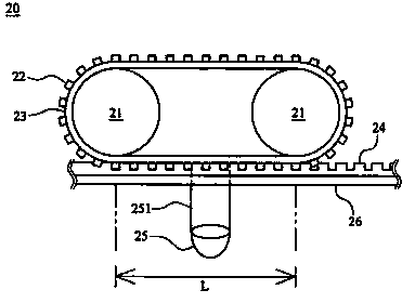
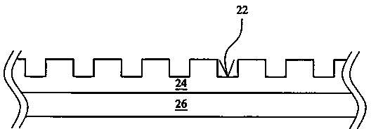
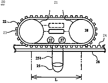
[0015] As shown in the figure, the improved roller embossing device of the present invention is characterized in that: the improved roller embossing device 20 includes a plurality of driving rollers 21 and a belt body 23, the former are arranged at intervals, and the outer side of the latter is arranged There is at least one transfer structure 22, and the drive roller 21 is surrounded by the inner side to form a transfer area, and a curing device 25 is arranged at the extension position of the transfer area L; the improved roller imprinting device 20 also includes a substrate 24 , which is set on a working platform 26 , and the substrate 24 is in contact with one side of the belt 23 . The curing unit 25 can generate a curing source 251 in contact with a portion of the surface of the substrate 24 . The belt body 23 can be a ring-shaped film, and the transfer struc...


PUM


Abstract

The invention discloses an improved roller impressing device. The device is characterized in that: the improved roller impressing device comprises a plurality of transmission rollers and a belt body, the transmission rollers are alternately arranged, the external side of the belt body is provided at least a transfer structure, the inner side of the belt body encircles the transmission rollers so as to form a transfer zone, a solidifying device is arranged on an extended position of the transfer zone; and the improved roller impressing device also comprises a basic material, which is arranged on a workbench and contacts one side of the belt body. The improved roller impressing device has the advantages that: the contact distance and contact time between the transfer structure and the basic material are increased so as to avoid the generation of phenomenon of transfer structure transformation and side wall disintegration, when the transfer printing is incomplete or in the demoulding process.

Description

technical field [0001] The invention relates to an embossing device, in particular to an improved roller embossing device. Background technique [0002] In recent years, with the vigorous development of optoelectronic technology, the demand for consumer electronics products is increasing, and at the same time, it is also developing towards miniaturization. These products all need to form nanostructured components on the surface of the product, such as: mirror microstructure components, microlens molds Or diffractive optical elements, etc. However, traditional microlens arrays require expensive equipment to manufacture, and at the same time, the manufacturing process is complicated, the manufacturing cost is too high, the manufacturing process takes a long time, and it cannot be mass-produced. Therefore, how to develop mass production technology is really important. Although the photoresist-coated platen imprinting system of the nanoimprint process is the first devel...

Claims


Application Information

Patent Timeline
IPC IPC(8): B29C59/04B82Y40/00
Inventor 朱科奇
Owner 宁波市鄞州科启动漫工业技术有限公司
Learn More