Hydraulic unit for vehicle brake system with motor bearing

A technology for hydraulic equipment and vehicle braking, applied to shafts and bearings, rigid brackets of bearing components, brakes, etc., can solve the problems of knocking noise, vibration of the drive motor, affecting NVH characteristics, etc., to avoid joint gaps, avoid Vibration, effect of improving NVH performance

Active Publication Date: 2014-03-26
ROBERT BOSCH GMBH
View PDF7 Cites 6 Cited by
  • Summary
  • Abstract
  • Description
  • Claims
  • Application Information

AI Technical Summary

Problems solved by technology

As a result, vibrations occur at the drive motor, which in particular cause rattling noises and adversely affect the so-called NVH properties of the vehicle

Method used


Image

  • Hydraulic unit for vehicle brake system with motor bearing
  • Hydraulic unit for vehicle brake system with motor bearing
  • Hydraulic unit for vehicle brake system with motor bearing

Examples


Embodiment Construction

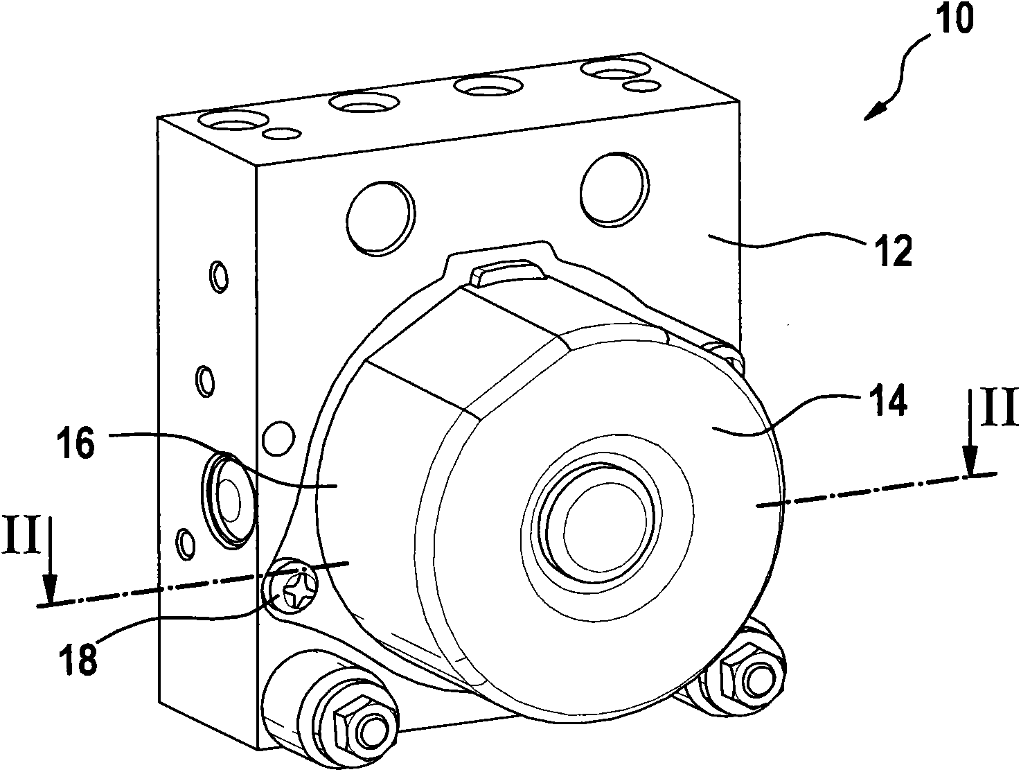
[0024] figure 1 and 2 A hydraulic system 10 of a vehicle brake system (not shown) is shown, which comprises a square hydraulic block 12 and a drive motor 14 which is fastened externally to this hydraulic block 12 . The drive motor 14 has a cup-shaped motor housing 16 , which is fastened in a conventional manner to the side of the hydraulic block 12 by means of at least two screws 18 and thus holds the drive motor 14 on the hydraulic block 12 .

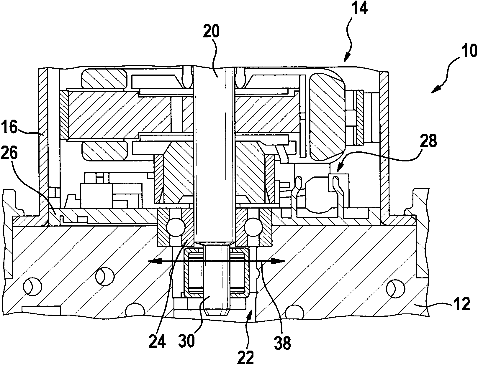
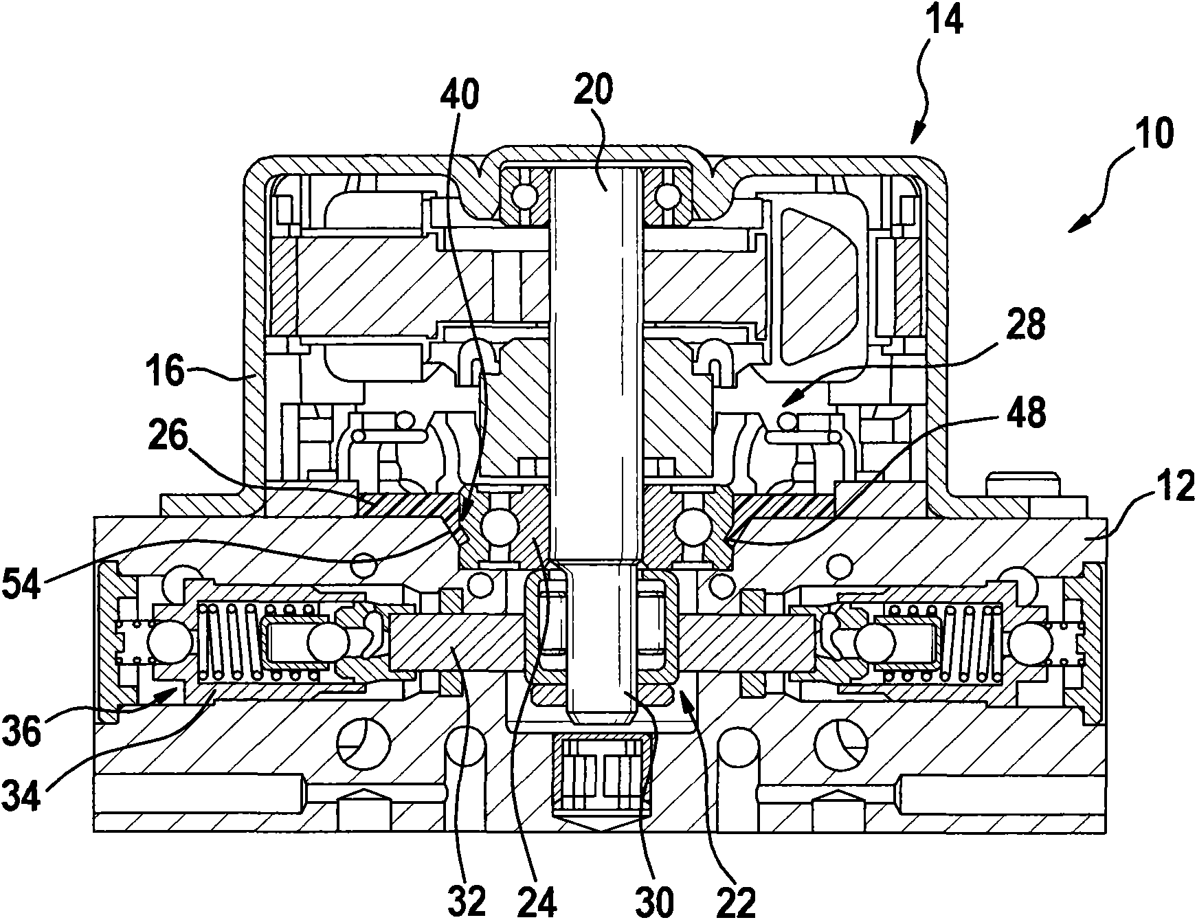
[0025] The drive motor 14 drives a motor shaft 20 , which protrudes through a bore 22 into the hydraulic block 12 and is mounted in the hydraulic block 12 by means of a motor shaft bearing 24 . Furthermore, bearing caps 26 are provided as A bearing caps for delimiting the motor interior 28 , for accommodating the motor shaft bearing 24 and for pre-centering the drive motor 14 prior to assembly on the hydraulic block 12 .

[0026] Attached to the motor shaft 20 is an eccentric 30 which, during operation, rotates together with the moto...


PUM


Abstract

The invention relates to a hydraulic unit for vehicle brake system with motor bearing, and provides a hydraulic unit (10) of a vehicle brake system having a hydraulic block (12) and a drive motor (14) externally arranged on the hydraulic block (12) for driving at least one pump element (36) and a motor shaft (20) is supported on the hydraulic block (12) by means of a motor shaft bearing (24), the motor shaft bearing (24) is fixed to the hydraulic block (12) with a wedge member (40).

Description

technical field [0001] The invention relates to a hydraulic system of a vehicle braking system with a hydraulic block and a drive motor, which is arranged on the outside on the hydraulic block for driving at least one pump element and whose motor shaft is supported by means of a motor shaft bearing on the hydraulic block. Furthermore, the invention relates to the use of such a hydraulic device in a vehicle braking system. Background technique [0002] A hydraulic system is used in a vehicle brake system to be able to provide a brake pressure regulated by means of brake fluid in an associated brake circuit. For adjusting the brake pressure, the hydraulic system includes a hydraulic block or a block-shaped housing in which a plurality of bores are arranged. These housings also serve as pump housings for the corresponding pump elements. The individual pump elements are formed by a pump piston and a pump cylinder, in which the pump piston is mounted so as to be movable back a...

Claims


Application Information

Patent Timeline
Patent Type & Authority Applications(China)
IPC IPC(8): B60T17/02
CPCB60T8/368B60T17/02F16C27/066F16C35/077B60T8/34B60T13/74
Inventor W·舒勒
Owner ROBERT BOSCH GMBH
Why Eureka
Try Eureka